L1 has no real effect on the amp bandwidth. The L1/R3 ratio determine the feedback ratio and thus the gain, and you wonder what happens with increasing frequency when the L impedance rises. But look at the other branch of the bridge; the C is juxtaposed and it's impedance will decrease with frequency, so the bridge balance is maintained over the whole frequency band! And as can be seen in the calculations, bridge balance will ensure that the dumpers' gain variation (which is its distortion of course) is cancelled out.
BTW the C in the bridge does double duty as the miller compensation cap for the class A driver amp.
This is one hell of a smart circuit! It is very hard to understand intuitively (or at least for me it is). I had to work through Walker's original article and the critique by Lipshitz and Vanderkooy several times to start to understand what's going on there!
Jan
Last edited:
Yes. Please indulge me, I love this stuff ;-)
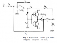
Assume the dumpers are off. Then there is no signal across Z4 and the feedback through Z1 sets the gain.
Now assume the dumpers conduct. The dumper current creates a signal across Z4 which increases the feedback through Z1 which decreases the current output from the Gm stage*. This decrease in current is - with bridge balance - exactly the same as the increase in current from the dumpers. So the system gain does not vary whether the dumpers are on or off, so any irregularity in the dumper gain does not impact the system output!
The second stroke of genius was making Z2 a capacitor which then doubles for the miller comp cap, and then make Z4 an L to maintain bridge balance over frequency.
* The class A driving amp is a transconductance stage which provides output current, not output voltage.
http://4tubes.com/3-BOOKS/BOOKS-LIT...Current dumping - does it really work DCD.pdf
Jan
Attachments
Last edited:
I do not intend to change definitions. I referred to the driver stage as it is very indicative of the class of an amplifier.jan.didden said:With all due respect Ed, it's hard to have a meaningful discussion if you use a private definition of class (A)B that differs from the definition for the rest of us.
I beg your pardon and that of readers if my previous posts were unsuitable for this thread.
I played around with a version of this concept during my linearization studies last year (minus the clever compensation networks). Omitting the compensation, this is similar to the emitter follower enhanced Sziklai pair shown in Art of Electronics X Chapters (p127). One difficulty I faced is that every time I put in local current limitting, it passed the current limitting problem upstream. So I had to add more reverse polarity and current limitting to each section than I anticipated.
On the other hand, one great thing about the concept is that during normal operation it does not pass base currents from the output stage upstream. I found that the local floating VBE linearization concept I was proposing elsewhere provides about 20dB of benefit before the non-linear base currents pass through enough to cause their own issues with VAS distortion. I think these concepts could be combined to provide amazing overall output stage performance.
I will have to work harder to analyze whats going on with all the feedback paths. Is the connection back to D1/D2 from the output a feedback path, a feedforward path, or maybe a bootstrap?
Last edited:
This is one hell of a smart circuit! It is very hard to understand intuitively (or at least for me it is). I had to work through Walker's original article and the critique by Lipshitz and Vanderkooy several times to start to understand what's going on there!
Jan
Jan,
Do you happen to have Walker's original article or the critiques by Lipshitz and Vanderkooy on hand? Maybe a link to a PDF?
I read the blogpost linked in the post #1, but what you mentioned sounds interesting. I'm not sure if they are available or not. Thanks.
There is a very good paper on post #23
Current Dumping, Class A Performance With No Idle Current
I do not fully understand the math in that paper though.😱
Here is my another try. EF3 without any bias. 0.003% THD@10KHz, impressive!

The extra resistor R6 is to compensate the present of the Miller cap C3.
Current Dumping, Class A Performance With No Idle Current
I do not fully understand the math in that paper though.😱
Here is my another try. EF3 without any bias. 0.003% THD@10KHz, impressive!
The extra resistor R6 is to compensate the present of the Miller cap C3.
Let us assume we have a Class AB amplifier that is underbiased such that in the output stage the current is almost zero. For the sake of clarity, let us assume the quiescent current in the output stage is 0.1mA per transistor. Although, such an amplifier is technically Class AB, due to being underbiased it behaves much like a Class B amplifier with considerable cross-over distortion.
My tempting question is: Can cross-over distortion be removed using the current dump principle? If the answer is yes, adding additional circuitry to use current dump would simplify its bias setup. Furthermore, if current dump is very efficient at removing cross-over distortion, it would make sense to build underbiased Class AB amplifiers which behave like Class B but with additional circuitry to implement current dump.
My tempting question is: Can cross-over distortion be removed using the current dump principle? If the answer is yes, adding additional circuitry to use current dump would simplify its bias setup. Furthermore, if current dump is very efficient at removing cross-over distortion, it would make sense to build underbiased Class AB amplifiers which behave like Class B but with additional circuitry to implement current dump.
Well the whole idea of current dumping is that you do not need any biasing of the output stage without getting crossover distortion! So why spend money and effort for something that you worked hard for to not need in the first place??
Very first hit on Google:
http://4tubes.com/3-BOOKS/BOOKS-LIT...Current dumping - does it really work DCD.pdf
Walker's original article:
http://www.keith-snook.info/wireles...d-1975/Current Dumping Audio Amplifer DCD.pdf
Jan
Very first hit on Google:
http://4tubes.com/3-BOOKS/BOOKS-LIT...Current dumping - does it really work DCD.pdf
Walker's original article:
http://www.keith-snook.info/wireles...d-1975/Current Dumping Audio Amplifer DCD.pdf
Jan
Last edited:
I am a person who seeks simplicity where it is possible. A small auxiliary Class A output stage with its output in parallel of a much larger Class B output stage, should work provided the small auxiliary output stage is quick enough to supply current to the output at crossover of the Class B output stage. So, I think, there is no need of additional complexities. I would opt to use normal negative feedback as in a normal Class AB amplifier without the additional complexity. In my humble opinion there is no need to implement a circuit which intervenes only at crossover, and there is no need of bridges.
Last edited:
I would opt to use normal negative feedback as in a normal Class AB amplifier without the additional complexity. In my humble opinion there is no need to implement a circuit which intervenes only at crossover, and there is no need of bridges.
I have done lots of simulations. My observation is that the THD with "Current Dumping" configuration is much lower than a "Blameless" style Class AB with the same idle current. Almost 10dB lower on average.
PS: The "idle current" of the "Current Dumping" amp is the current on Class A portion. The Class B portion has No idle current.
I think the reason is that. In "Current Dumping" configuration, the Class A portion is some kind of bootstrapped by the Class B output stage. The Class A portion never runs out of current. Thus, the Class A stage works the whole cycle of the sin wave. That is the major difference than a normal Class AB amplifier.
Last edited:
I am a person who seeks simplicity where it is possible. A small auxiliary Class A output stage with its output in parallel of a much larger Class B output stage, should work provided the small auxiliary output stage is quick enough to supply current to the output at crossover of the Class B output stage. So, I think, there is no need of additional complexities. I would opt to use normal negative feedback as in a normal Class AB amplifier without the additional complexity. In my humble opinion there is no need to implement a circuit which intervenes only at crossover, and there is no need of bridges.
You'd have to be very careful about Nyquist stability. Two abruptly-switching forward paths would have different gain characteristics.
Is there any mileage in adding error-correction via the "other" speaker terminal (perhaps in a feedforward fashion)? So neither speaker terminal is grounded.
Simulating my version of "current dump" proved that instability is an issue. Furthermore, although my reasoning seems logically justified, it did not work, even in simulations. Maybe, I need to take more time and do many more trials like Edison, but is it worth the effort? A VBE multiplier works, and is simple to implement. If I even convince myself to get a Class A amplifier, I will opt for low power, but my ears are getting older by the year, and it does not seem I will benefit from using Class A. Class AB is more than enough.keithj01 said:You'd have to be very careful about Nyquist stability. Two abruptly-switching forward paths would have different gain characteristics.
Truly, this forum is frequented by some very knowledgeable and experienced engineers and technicians. Listening to their advice can save hours upon hours and many headaches for anyone interested in DIY audio.
I've also experimented with a trimmer cap and trimmer resistor in the bridge, and you can really tune it for unmeasurable distortion. So it is important to use accurate value parts in the bridge.
Jan
I am interested in where you put the trimmers
As I said, in the bridge. Replaced the C with the cap trimmer. Replaced the R in the other leg with a resistor trimmer.
Jan
Jan
I was interested to know how your trimming varied from that used by Vanderkooy and Lipshitz in their analysis.
It's very long time ago that I did this, and I don't remember all details.
I know that I varied the capacitor and the resistor, and could see that the distortion varied. I was a bit disappointed that it was hardy possible to get a deeper null, but that is more a testament to the ingenuity of the circuit I guess.
Jan
I know that I varied the capacitor and the resistor, and could see that the distortion varied. I was a bit disappointed that it was hardy possible to get a deeper null, but that is more a testament to the ingenuity of the circuit I guess.
Jan
It's very long time ago that I did this, and I don't remember all details.
I know that I varied the capacitor and the resistor, and could see that the distortion varied. I was a bit disappointed that it was hardy possible to get a deeper null, but that is more a testament to the ingenuity of the circuit I guess.
Jan
"Deep Null" is hard, even in the simulation (for me). When I get "Deep Null", the THD is around 0.001% or near -100dB @ 10KHz in the simulation.
However, I find it is relatively easy to get "Mostly Null" with 2% tolerance parts. The THD is around 0.003% or -90dB in the simulation.
On the nulling bridge, for resistors and cap, you can get 1% tolerance parts easily; For the inductor, I believe you have to make by yourself, a good LCR meter is helpful. 5% tolerance is good enough.
You also need to include input stage transistor's re into your bridge. I find it will mess up the balance of the bridge a little bit. To get away this, use CFP (Sziklai pair) as input stage instead of single transistor. With CFP, the equivalent re is beta times smaller as that of a single input transistor.
Depends on your goal, for me, I won't bother to fine tune the bridge once it is built.
Last edited:
I seem to remember reading that QUAD measured each L and selected a resistor for it and treated them as a pair. Not sure where that was, maybe someone has the same recollection?
And lets not forget, getting it down to -100dB with zero bias current is a remarkable feat.
Jan
And lets not forget, getting it down to -100dB with zero bias current is a remarkable feat.
Jan
- Home
- Amplifiers
- Solid State
- Current Dumping, Class A Performance With No Idle Current