ive been looking into this part of the circuit in a bit more detailSo as we have done before, take a step back and recheck a few things.
If the breakers are OK then you should see the same voltage across R635 as you do R631 because they are effectively in parallel. There should be a small voltage present.
Do both channels work OK?
R661 and 662 by-pass the thermal breaker.
If the thermal breaker fails or goes open circuit am i right in assuming R662 is designed as a secondary fail safe? or am i looking at this wrong
the reason is both R662 AND R 661 look like they run realy hot.They are both in value/tolerance but are quite black in the middle.
is it worth upping the wattage value to 1w from 1/2w? i would imagine this amp has been driven quite hard for long periods in the past, or are they blackened for another reason?
all of the components around it in cicuit appear ok and the amp does work ok.
L601 and L602 are induction coils?-what is thier purpose here? im not that up on induction yet.
L601/2 are referred to as "output inductors" or "output coils" and the function is to attenuate small reflected signal impulses from the loudspeaker coil. To be effective, there is usually also a small value damping resistor, ~ 5R in parallel too. The need for this is that the reflected signal can play havoc with the feedback and increase distortion + instability. Some designers omit them and some designs are more or less susceptible but since B.E.E. thought they were necessary in 3020 design, let's also assume they are.
Last edited:
R661/2 are really the main feedback resistors and these connect after the breaker. The idea is that any non linearity in the breaker (poor contacts etc) is compensated for by being included within the feedback loop.
R635 and 636 maintain feedback if the breaker trips open circuit. If this was not done then the amp output would swing toward one of the rails and do bad things.
The inductor has the effect of providing a rising impedance with frequency and helps isolate the output from capacitive loading such as by using certain oddball speaker cables.
If the direct output (before the inductor) is loaded with a small cap (say 10nF) then many amplifier will burst into destructive oscillation.
The breaker should normally appear as a short circuit. The contacts are closed.
The difference in voltage between Q601 emitter and Q615 emitter will be the same as the voltage you see across the resistors.
So if Q601 E is at minus 1v and Q615 E is at plus 0.1 volt then you will measure 1.1 volts across each resistor.
If the breaker is open (tripped or faulty) then you would still read 1.1 volt across R635 and essentially zero volts across R661 if no load is present. This is because the diagram shows only R701 (220k) as a DC path.
Its just ohms law and series and parallel resistors")
Do you understand how the feedback take off point works and how it can compensate for problems and non linearities in things like the breaker contact?
The difference in voltage between Q601 emitter and Q615 emitter will be the same as the voltage you see across the resistors.
So if Q601 E is at minus 1v and Q615 E is at plus 0.1 volt then you will measure 1.1 volts across each resistor.
If the breaker is open (tripped or faulty) then you would still read 1.1 volt across R635 and essentially zero volts across R661 if no load is present. This is because the diagram shows only R701 (220k) as a DC path.
Its just ohms law and series and parallel resistors
Do you understand how the feedback take off point works and how it can compensate for problems and non linearities in things like the breaker contact?
'Do you understand how the feedback take off point works and how it can compensate for problems and non linearities in things like the breaker contact'
kind of,not realy THB some of the stuff you guys talk about is a bit further down the line for me i guess
Im getting better identifying series/parallel in circuits, some still isnt clear to me as it mainly the way some have been drawn
kind of,not realy THB
some of the stuff you guys talk about is a bit further down the line for me i guessIm getting better identifying series/parallel in circuits, some still isnt clear to me as it mainly the way some have been drawn
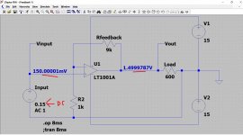
Lets try this then, a simple amplifier using one opamp. You can think of most power amps as just big opamps and they follow most of the same rules. These are a great way of learning a lot of the basics.
Lets look at two things, the gain and feedback.
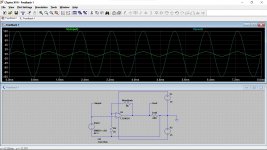
If you run this simulation and look at the input voltage and also the output voltage you will see it has a voltage gain of 10. So 1 volt in gives 10 volts out.
Remember this rule:
The output of an amplifier with feedback applied will do whatever is needed to keep the difference in voltage between the two inputs at zero.
(we are ignoring tiny offsets and such like here)
All the power amps like your NAD and the Europa actually have two inputs, a + or non inverting one and a - or inverting one.
The basic voltage gain of all the power amps and the opamps is massive, it is many thousands of times and we control and set the gain by feedback to make it exactly what we want.
So look at the simulation. Can you see now why the output goes to 10 volts when we apply 1 volt.
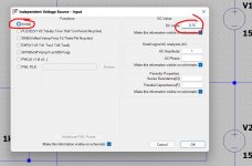
If you change the input voltage to a DC value you can test the theory and practice. Change the sim input to +0.15v and -0.27 volt as here by right clicking it and selecting 'None' and entering a DC value.
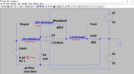
So from the two values of resistor you can work out what the actual amplifier voltage will be. Lets test the theory and try and calculate the output voltage for the following.
Vin = 0.26 volts DC
Rfeedback = 6853 ohm
R2 =479 ohm
These were all picked at random.
So the rule above says the output will do what is needed to make the difference between the inputs zero.
We know we have 0.26 volts on the + input and so we know we will need that same voltage on the - input to keep the difference between them at zero. So what must the output voltage be to do that?
Ohms law. We need to calculate the current in the 479 ohm and that is 0.26/479 giving 0.000542A or 0.542 milliamps.
That same current will flow in the 6853 ohm because the two resistors are in series (note... the opamp inputs do draw a minisule current bit it is so low we can ignore it).
So we calculate the voltage across the 6853 ohm and that is 6853*0.000542 giving 3.719 volts.
The total voltage across the two resistors is 3.719 volts plus the 0.26 volts giving 3.979 volts.
Does it work... yes it does.
Lets look at two things, the gain and feedback.
If you run this simulation and look at the input voltage and also the output voltage you will see it has a voltage gain of 10. So 1 volt in gives 10 volts out.
Remember this rule:
The output of an amplifier with feedback applied will do whatever is needed to keep the difference in voltage between the two inputs at zero.
(we are ignoring tiny offsets and such like here)
All the power amps like your NAD and the Europa actually have two inputs, a + or non inverting one and a - or inverting one.
The basic voltage gain of all the power amps and the opamps is massive, it is many thousands of times and we control and set the gain by feedback to make it exactly what we want.
So look at the simulation. Can you see now why the output goes to 10 volts when we apply 1 volt.
If you change the input voltage to a DC value you can test the theory and practice. Change the sim input to +0.15v and -0.27 volt as here by right clicking it and selecting 'None' and entering a DC value.
So from the two values of resistor you can work out what the actual amplifier voltage will be. Lets test the theory and try and calculate the output voltage for the following.
Vin = 0.26 volts DC
Rfeedback = 6853 ohm
R2 =479 ohm
These were all picked at random.
So the rule above says the output will do what is needed to make the difference between the inputs zero.
We know we have 0.26 volts on the + input and so we know we will need that same voltage on the - input to keep the difference between them at zero. So what must the output voltage be to do that?
Ohms law. We need to calculate the current in the 479 ohm and that is 0.26/479 giving 0.000542A or 0.542 milliamps.
That same current will flow in the 6853 ohm because the two resistors are in series (note... the opamp inputs do draw a minisule current bit it is so low we can ignore it).
So we calculate the voltage across the 6853 ohm and that is 6853*0.000542 giving 3.719 volts.
The total voltage across the two resistors is 3.719 volts plus the 0.26 volts giving 3.979 volts.
Does it work... yes it does.
Attachments
And referring back to your NAD...
The + or non inverting input is the base of Q601. The - or inverting input is the emitter of Q601.
The feedback network is R661 and R635 (which are in parallel if the breaker is OK) and R631 forms the feedback return which would be R2 in the opamp circuit.
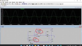
So the parallel resistors have a combined value of 387 ohm. Lets put these values into the sim. With an AC voltage of 0.1 volts applied we have an output of what looks like 1.5 volt (looking visually at the trace). So the voltage gain is about 15.
There is a simple formula for gain for this. Look at the opamp circuit.
It is (Rf/R2)+1 so we had (9000/1000)+1 giving 10
For the NAD it would be (387/27)+1 which is 15.3
So the theory and the practice work
If you look at any amplifier you should be able to identify the basic feedback network and so make a good estimation of the gain. We have ignored the caps and how they effect things at this point. Up to now we are looking at it as all DC coupled.
The + or non inverting input is the base of Q601. The - or inverting input is the emitter of Q601.
The feedback network is R661 and R635 (which are in parallel if the breaker is OK) and R631 forms the feedback return which would be R2 in the opamp circuit.
So the parallel resistors have a combined value of 387 ohm. Lets put these values into the sim. With an AC voltage of 0.1 volts applied we have an output of what looks like 1.5 volt (looking visually at the trace). So the voltage gain is about 15.
There is a simple formula for gain for this. Look at the opamp circuit.
It is (Rf/R2)+1 so we had (9000/1000)+1 giving 10
For the NAD it would be (387/27)+1 which is 15.3
So the theory and the practice work
If you look at any amplifier you should be able to identify the basic feedback network and so make a good estimation of the gain. We have ignored the caps and how they effect things at this point. Up to now we are looking at it as all DC coupled.
Attachments
Something you can try...
Alter the NAD sim to show the two separate resistors and the breaker. Connect them as they are in the NAD with one resistor before the breaker and one after. You can use a 0.01 ohm for the breaker for now to simulate a near perfect contact.
Have fun
Alter the NAD sim to show the two separate resistors and the breaker. Connect them as they are in the NAD with one resistor before the breaker and one after. You can use a 0.01 ohm for the breaker for now to simulate a near perfect contact.
Have fun
The voltage gain is numerically '10' and so all you do is multiply the input voltage by 10 to get the output voltage. Nothing more complex than that.
It does not matter if you are looking at a 1 volt peak sine input (you get a 10 volt peak sine output) or a DC voltage applied to the input. For example -0.5 would give -5 volts output.
V1 and V2 are the supply voltage and -/+15v is a typical opamp supply. It does not matter if the supplies are changed or are uneven. For example +20v and -10v rails or +10v and -20v. The gain of the circuit is unchanged.
Where the supply voltage does matter is that you must have enough voltage to cover the expected output range. So if you have a 1v peak input and set the supply to +5 and -20 then you will find the output clips on the positive half cycle (it can not go higher than the supply) but the negative half is OK.
Try it.
In your sim with 50 volt rails you can get away with doing that but the real opamp would have exploded
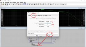
Remember the equation for voltage gain in db, the 20log(Output/Input).
So with 10 volts output and 1 volt input we have a gain of 20db.
If you set LT up like this we can plot the gain vs frequency. We can start at 1Hz and go to 1Mhz here.
Set the sim up like this and place the new command onto the workspace. Then run it. The gain is 20db, just as the theory predicts (the solid line, the dotted one is phase) but you can see it starts to fall away at high frequency, just like a real circuit would.
Attachments
- Home
- Amplifiers
- Solid State
- NAD 3020 problem