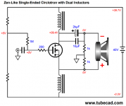
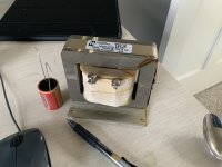
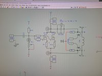
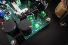
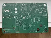
This design is taken from TubeCad.com. 6watts @ 8 ohms. Serious Iron for 6 watts. See Attached images for some enjoyment  I designed this amp to replace my 2a3 Set.
Dwight
I designed this amp to replace my 2a3 Set. Dwight
Attachments
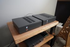
Cool amp! Is that a monoblock? I am working on something similar with dual inductors except they are coupled. Aiming for 100w SE Class A in balanced mode.
SuSyLu Where Are You?
SuSyLu Where Are You?
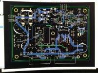
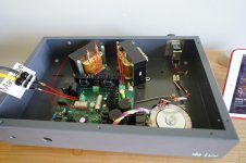
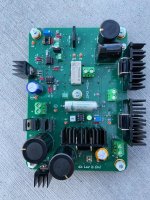
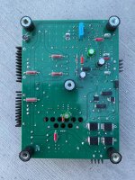
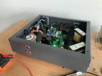
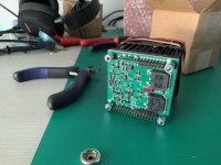
It’s been awhile but here is round #2
A Power op amp for the dc supply(fan cooled) and bolted the mosfets to the case. I have noticed as the freq goes down , the ripple (dc side) from the load inductor increases. Since inductors are differential , both sides ‘wiggling’ is not bueno.. hopefully @ 12w @ 8/4 ohms. I feel have the class A heat issues under control..
Datasheet - Power Amp Design
Dwight
Attachments
Nice build!
Do you like it?
I have built several versions of this and Solhaga has several threads about his SLAPS builds. They are the best sounding amps I have ever heard, so if your amps are anything like his I guess you are very happy with them.
Why did you use two separate coils? If you wind them bifilar you get a very efficient Feed Forward Error Correction.
Thanks !
I luv the sounds. The most enjoyable amp I have ever heard. My current solid state AB amp is being shipped to a family member. The next design will be using these high freq inductors from Hammond. I have no plans to fix my DOA 2A3 SET.
https://www.hammfg.com/files/parts/pdf/197J5.pdf
Could you share a link for the feed forward correction concept ?
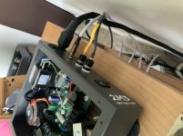
Also attached a pic of the high power op amp. Just received them.
Dwight
I luv the sounds. The most enjoyable amp I have ever heard. My current solid state AB amp is being shipped to a family member
. The next design will be using these high freq inductors from Hammond. I have no plans to fix my DOA 2A3 SET. https://www.hammfg.com/files/parts/pdf/197J5.pdf
Could you share a link for the feed forward correction concept ?
Also attached a pic of the high power op amp. Just received them.
Dwight
Attachments
Last edited:
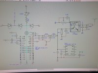
This design is taken from TubeCad.com. 6watts @ 8 ohms. Serious Iron for 6 watts. See Attached images for some enjoyment
Interesting. I thought about it and decided that the performance could
be identical with only one inductor, since both are in series with the power supply.
So I ran a simulation of the circuit which set one one inductor to 0 and doubled the
value of the other, and the waveforms were the same.
Is it possible that I have made an error?
There is a subtle difference due to the bias resistors. If you double the drain inductor and zero the source, the potentials are different as the bias resistors see different potentials.
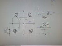
This second variant reduced the distortion by a factor of about 5 which I have not investigated further, but it seems related to the bias network and potential feedback loops as the power supplies float. This seems to be related to the split grounding resistor across the load too and how the two networks interact.
If further investigation confirms the improvement then it would be worth a single inductor in each channel!
Last edited:
I believe the original article in TubeCad said something like the inductors didn't need to be near as large as you might think. So I wonder what would the minimum inductor value be for a version of this amp if used only above 200hz ? in that case might 2 pair of 2mh air core inductors work ?
My server was down for some hours and the diyaudio forum software discovered it and changed the link to an error message.None of your images shows up.
Why post a link to thread missing images?
But if you click on the text "An externally hosted image", you will be able to see the image.
So I ran a simulation of the circuit which set one one inductor to 0 and doubled the
value of the other, and the waveforms were the same.
With a bifilar winded inductor you get an effective feed forward error correction - somewhat similar to SUSY. With the load coupled between the two windings - not directly to ground - you get a very stable amp without all the loudspeaker reactive behavior effecting ground and the amps working via the powersupply.
It does not (easily) show up in simulation, but it does make a large difference in real world listening tests.
The XSLAPS is even better in this regard.
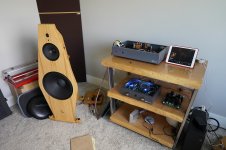
Recently compared my amp to a 845 SET that I also own. I found that the 845 SET was more spacious / transparent. To be honest , it was wasn’t a huge amount but it was enough to dig a little deeper..
1). The current inductors are designed for 60hz filtering. Not sure what the Q is @ higher frequency. I don’t own a bench top LCR meter so I am only guessing at this point. Hammond offers higher frequency inductors which I have obtain for comparison.
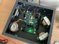
2) the voltage regulator cannot dampen all the ‘reflected /transmitted’? energy from the inductor. Also , the larger the capacitance on the supply, the ‘smaller’ the sound field became. The voltage regulator is from Sparkoslabs. I ended up removing all the capacitance except the 10uf on the VREG. I feel I need to hold the voltage with an strong fist since the inductor is differential creature. If both sides are ‘wiggling’ , you get nothing in return. The only power op amp that I found is the PAD137. It’s rail to rail , can handle a ton of current , and unity gain stable.. fingers crossed on that last item @ $235/each wish me luck !
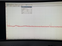
I have attached a couple pics. I only own a 16bit picoscope that is single ended. With the floating power supply , the ground plane is not idea. I have a differential scope on order but it’s back ordered. I have not included any output fft’s since the output is differential.
1). Unloaded power supply. FFT @ 4096 @ 20khz scale.
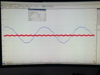
2). 1k @ 1v. Red is vreg. Blue is raw dc.
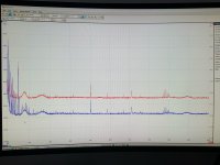
3). FFT’s for #2. Each color has its own scale. The software is a bit weird.
Dwight
1). The current inductors are designed for 60hz filtering. Not sure what the Q is @ higher frequency. I don’t own a bench top LCR meter so I am only guessing at this point. Hammond offers higher frequency inductors which I have obtain for comparison.
2) the voltage regulator cannot dampen all the ‘reflected /transmitted’? energy from the inductor. Also , the larger the capacitance on the supply, the ‘smaller’ the sound field became. The voltage regulator is from Sparkoslabs. I ended up removing all the capacitance except the 10uf on the VREG. I feel I need to hold the voltage with an strong fist since the inductor is differential creature. If both sides are ‘wiggling’ , you get nothing in return
. The only power op amp that I found is the PAD137. It’s rail to rail , can handle a ton of current , and unity gain stable.. fingers crossed on that last item @ $235/each wish me luck !I have attached a couple pics. I only own a 16bit picoscope that is single ended. With the floating power supply , the ground plane is not idea. I have a differential scope on order but it’s back ordered. I have not included any output fft’s since the output is differential.
1). Unloaded power supply. FFT @ 4096 @ 20khz scale.
2). 1k @ 1v. Red is vreg. Blue is raw dc.
3). FFT’s for #2. Each color has its own scale. The software is a bit weird.
Dwight
Attachments
-
 35B79D12-14F6-4D07-84E4-D3B12C5F7643.jpg776.8 KB · Views: 160
 -
 F4BF19E9-4AE0-4473-95E9-E37F33A0C4AB.jpg784.1 KB · Views: 145
 -
 E88BF0BF-36E9-4863-A72A-2D35D65953DB.jpg819 KB · Views: 159
 -
 3C5D8FDD-8960-4D88-BA9A-7E509856B3C5.jpg502.6 KB · Views: 153
 -
 DDB74B2B-3C32-4471-9471-EBF7B882CFF5.jpg883.4 KB · Views: 150
Last edited:
Are you saying that this is really a transformer and not two separate inductors?
Happyrabbit seems to be using two separate coils. My SLAPS and XSLAPS designs uses a singe bifilar winded coil that acts as a 1:1 transformer between the two windings for some Feed Forward Error Correction.
- Home
- Amplifiers
- Solid State
- A Zen Split Load Amp