I know simulations with MOSFETs and transformers can be optimistic, and I have not done any investigation into the accuracy of this, but a first run through a circuit with a twin transformer 50mH load biased at 2.5A and running from 40V (yes, 100W would be a massive dissipation for a single FET, but this is just a "what if" exercise) and comparing with Nelson's suggestion of a single 100mH coil both gave around 0.8% THD at 19W output.
But if you are going to use a transformer with 2 coils, the speaker can be earthed, and the transformer rated at 2:1 reduction with the secondary connected in series with the source. That provides ordinary negative feedback and a gain of 2 like the original, but THD was only 0.25%. And a stereo version would only need a single PSU.
This means that the transformer would have to be wound in layers or trifilar with the primary consisting of two coils in series for good magnetic coupling.
As I mentioned I haven't pursued this in any detail but it does seem that a more conventional approach might be able to give lower distortion. May be worth looking into further.
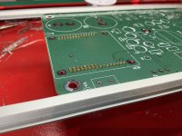
Finally making progress. A bit anxious over mounting the op amp.. snapped in without issue ! I lost a couple pin sockets to the carpeting but otherwise painless. I think I checked the spacing ~6x just to be sure. 😉
Dwight
Dwight
Attachments
Happyrabbit , using those 5mh inductors do you know the 3db low frequency cut off and damping factor ?
At ~1w it was flat from 20hz -20khz. Not sure that helps you much. The picoscope is a bit clunky plus the signal generator stops @ 20khz..Happyrabbit , using those 5mh inductors do you know the 3db low frequency cut off and damping factor ?
That's interesting and didn't the original article say something about you could use fairly small inductors so I just wonder how darn small an inductor you could use if you were only going to use it for a midrange amp.At ~1w it was flat from 20hz -20khz. Not sure that helps you much. The picoscope is a bit clunky plus the signal generator stops @ 20khz..
I looked at Neumann schematics but didn’t know about their multi-coil transformer reducing distortion.
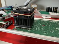
operational. buzz @ 1’ can be heard with 97db speakers otherwise lovely.. wasting the heat into the case seems to work well for my power levels. The fan is too loud.. need to slow it down a bit ! 1st attempt using an idea diode bridge controller..the bridge mosfets are room temp. Very cool 😎
dwight


dwight
Here it is with 6mh inductors (@2amps). I prefer the sound over the higher 20mh inductors. Not sure why ?That's interesting and didn't the original article say something about you could use fairly small inductors so I just wonder how darn small an inductor you could use if you were only going to use it for a midrange amp.
Hi Circlomanen,Happyrabbit seems to be using two separate coils. My SLAPS and XSLAPS designs uses a singe bifilar winded coil that acts as a 1:1 transformer between the two windings for some Feed Forward Error Correction.
I didn’t realize that a coupled 1:1 bifilar transformer provides Feed Forward Error Correction (FFEC). On my SuSyLu amp, I have such an arrangement. Are you saying FFEC is same as SuSy (SuperSymmetry)?
@happyrabbit,
Your amp looks great. Very neat PCB and lots going on under the hood of that fan cooled heatsink. I like the simple clean look of your (steel ?) chassis.
3.3mm Aluminum. I also changed the fan to a Noctua. The stock fan was crazy noisy.
Just realized Hammond manufactures these.. sector wound not Bifilar. Wire one of the legs out of phase and I should have it ? Very interesting 🤨 its only $30 And in stock too.
https://www.hammfg.com/files/parts/pdf/196Q2.pdf
dwight
Just realized Hammond manufactures these.. sector wound not Bifilar. Wire one of the legs out of phase and I should have it ? Very interesting 🤨 its only $30 And in stock too.
https://www.hammfg.com/files/parts/pdf/196Q2.pdf
dwight
Last edited:
That looks like nice option to cut down to one inductor, reduce distortion, and probably increase current capability due to DC field saturation cancelling out.
Is that a standard aluminum NEMA enclosure (Hoffman etc) painted grey?
Is that a standard aluminum NEMA enclosure (Hoffman etc) painted grey?
That looks like nice option to cut down to one inductor, reduce distortion, and probably increase current capability due to DC field saturation cancelling out.
Is that a standard aluminum NEMA enclosure (Hoffman etc) painted grey?
https://www.protocase.com/
their software is different. Just updated my alibre software. Need to learn the sheet metal details.
Last edited:
Thanks for the link to this case vendor. Looks useful. What are prices like for the one you have ?
Using a power op amp as the dc supply definitely dampens the low freq energy from the inductors. 1v@1khz@7r.
1- raw power supply
2- raw power supply w/ 1khz
3- op amp output
see post #8 for the Voltage Regulator FFT’s.
dwight


1- raw power supply
2- raw power supply w/ 1khz
3- op amp output
see post #8 for the Voltage Regulator FFT’s.
dwight
Here is the output ftt @ 1v@1khz@7r. Not the best measurement. Using 2 single ended probes and then subtracting Plus it’s connected to a floating ground.. don’t beat me up too much 😉. I am still waiting on the differential Picoscope.
dwight


dwight
Well.. the cheap dual inductor works ! Wired with both channels (- & +) in phase. See attached. 2w @ 7ohms @ 1khz. measurements using a 16bit picscope + differential probe(1:10). 1st fft is the dual choke. 2nd fft is the HF inductors. Both inductors biased @ 2 amps.


- Home
- Amplifiers
- Solid State
- A Zen Split Load Amp