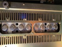
I recently bought an old TA-5650 amp in very decent condition and am in the process of cleaning and servicing it.
The amp appears to be a letter model, with the changes made in the Dutch service bulletin and with the wire wrap power leads instead of connectors.
I have replaced the suicide diodes and installed the double diode centre ground in the voltage doubler circuit.
Yesterday I measured the V-Fets and noticed that one of the 2SK60s (number 6) was showing a little high on the SD measurement of around 3.5 ohms. Am I looking at a shagged V-fet here ? If so, does anyone know if there is any place to source a 2SK60 with JC-54 grading?
Cheers,
Jon
Attachments
As posted on a link here 2 years ago --Little Diode sell them --judging by the price --£34 + VAT if they are not original build /design then the company would have big problems under the UK Sale of Goods Act.-
LittleDiode – Electronic Components for All
LittleDiode – Electronic Components for All
Thanks for that, I'd be happy enough giving it a go on that basis. UK seller and Sale of Goods Act gives you a bit of confidence.
I wonder how many you need to buy for a good chance of a match on the grade. I'm tempted to buy a few, measure, see what I've got and swap for a fit.
I wonder how many you need to buy for a good chance of a match on the grade. I'm tempted to buy a few, measure, see what I've got and swap for a fit.
Good luck and let us know how you make out!I wonder how many you need to buy for a good chance of a match on the grade. I'm tempted to buy a few, measure, see what I've got and swap for a fit.
Last edited:
Did you have any luck with this by any chance? I bought a 5650 without seeing it for a good price to restore. Having opened it up today it's actually completely short one 2SK60, so I could do with finding at leat one myself....")
Hi Elliot,
Turns out my FETs were fine after all. I replaced a couple of input Transistors to lower the DC offset and a couple of caps and then followed the installation process as per the service manuals and then set the bias (also replaced the 2.2K trimmers for multi-turn pots) and all worked great.
I did manage to score a matched set of 4x 2SJ18/2Sk60, used , from someone breaking a TA-4650 and these all measured good. Also got a set of 6 (4 SKs and 2 SJs) from another TA-5650 that was being parted, so I have a spare set of VFETs of 2 rankings (all ok so long as they are marched per channel).
Apart from the link above, the other genuine source i know of is Donberg in Ireland, Veronika is super helpful and may be able to get the odd one or two depending upon your ranking.
<vhona@donberg.ie>
What Rank do you need?
Also, before you do anything at all, remove the suicide diodes right now!.
If you do manage to get it working, you are in for a treat. The first play of mine blew me away! incredible staging and depth. Not tried the Phono stage yet, but that also has a couple of small V-Fets in there (I have a spare phono board from the 4650 so maybe will play with them in a pre-amp design).
J
Thanks for all the help guys, I've sent out emails to a few of the possible suppliers last night and will report back with what I hear.
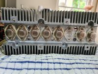
I've attached a picture of what I've got, the easy answer seems to be I need another JL-54 right? I've got a curve tracer and will run the rest through it today to test they're working.
Then, yes, absolutely, the suicide diodes are getting pulled and replaced. I'm doing that before it gets anywhere near some electricity
I'm actually really excited by it too, from everything everyone says it sounds like it's a bit special and I love that it's an early VFET design. I live abroad these days but I'm doing the restore at my family's place in the UK as I can finally visit again. There's no record player here so I won't get to try out the phono stage yet either, but they have a decent Linn system to run it through!
Attachments
Hi Elliot,
I decided to do a recap on my TA-5650 tonight, so the setup procedure is fresh in my mind.
Remove all the vfets and clean them well to remove the old schmoo off them. Use a ground strap to earth yourself just to be safe.
You need a 54 rank part, or 4 of the same rank to swap out on the channel.
I used the service manual method for testing them, all worked fine. Do short your probe leads 1st to get the lead resistance and subtract it from the readings.
With the vfets out and away somewhere safe and wrapped in tin foil, 1st thing to is the suicidal diode swap, followed by the voltage doubler mod for balanced voltage output.
If your amp has connectors for the power supplies to the main board, get rid of these and either wire wrap or solder the power leads to the amp board.
Replace the output relay, replacement omrons can be got easily enough. I got mine off eBay from a uk seller.
Assuming all is ok and you are feeling brave, power up the amp, make sure you plug in the centre connector to the amp board, this is the input signal and also needed for the relay board to work.
Once powered up you should hear the relay click in after around 8 seconds from cold start.
1 Check the voltages on the voltage doubler board, adjust VR1 to get 20v at q403 emitter, referenced to -ve speaker terminal.
2 check the dc offset with DMM between output terminals. Anything below 10mV is fine. Any problems here means you need to swap out the Q302/303 and Q352/353 on the amp board. Easy to source alternatives and they need matching for hfe.
3 assuming offset is ok, adjust the bias pots on amp board fully clockwise until vGS is max (29v or so)
You can probe the Source and Gate of the vfet connectors with -ve lead on -ve speaker terminal. Should read around 79v and 48v.
Now insert the vfets with new schmoo, sparingly. Cross fingers and hit the power switch. Don’t use a test bulb as it will cause you problems. Use a DMM, -ve on left ch + speaker output, +ve on the test point by the trim pot ( do use multi turn pots). It should read 0v. Check both channels.
Now with DMM connected, slowly wind the pot until you get a mV or so showing ( it will take a few turns until it starts) then wind it up to about 30mV, smefor other channel. You may hear the transformer start to hum as the vets start conducting. Leave it for 15-20 mins to warm up. Keep watching the bias and if it climbs over 50 mV wind it back. Once warm, set to 50mV and you are done.
Well done!
Do pull the service manuals from hifiengine and make sure you do the service updated in the Dutch update.
Pm me if you need help or advice.
Last edited:
Jon, that's an enormous help, really, that's very kind. I've got the idea for a recap as well down the line after I get it going, I hope it went / is going well! Would be interested to hear your thoughts on any difference it may make.
At the moment, one seller thinks they might be able to help on the FET, which is very positive. I didn't manage to test the others yesterday, I got caught up trying to get the curve tester's software working on a Mac and had a world of fun
I've read a fair few threads across the Internet about TA-5650 / 4650 restoration. Having everything written down as clearly as above will be a great reference for anyone wanting to get one going again.
I only recapped it due to the age and unknown history. Not expecting any changes and kept the main filter caps as they read good.
Great if you can get a 54 ranked replacement.
Easiest way to test is with a DMM on resistance setting and follow the service bulletin guides. No need to curve trace them as very unlikely you can get matched sets, and to be honest, they are probably all over the place as they will have aged over the 40 years of use, each slightly differently.
The Dutch service manual recommends replacing a number of Resistors and Caps, plus lower the bias to 50mv. Mine must be a fairly late model as it had the changes, plus had the terminals wire-wrapped.
I did convert mine to 4mm terminal posts as my speakers wires are terminated with banana plugs. There is a kit on eBay or buy some 2 mm acrylic sheet and make your own.
Give me a shout once you have it back together and have measured the dc offset. I have replacement transistors if the offset needs sorting.
Do you have a link to your curve tracer ? I also use a Mac and am interested in what your setup is.
Last edited:
Ah, I had thought there was a multimeter at my family's place but there isn't unfortunately. I've got to fly back in a couple of days so I don't think I'll be able to get much further until I come back closer to Christmas.
I've got a DCA75 curve tester, Peak Atlas DCA Pro model DCA75 | Peak Electronic Design Limited , I haven't used it loads but it seems pretty good for what it does. I wasn't able to make it work with the Mac though... The software is Windows based and needs a virtual desktop (which I didn't want to put on a machine that wasn't my own). I tried a Windows emulator called Wine but had no luck with that on the OS version of this Mac. I struggle with Macs though slightly as I'm not used to them.
Just reading off the measurements it takes and outputs on its screen seems to have been helpful though, even without the graphing aspect. Reading through this thread VFET testing method and result I realised that the tester measures the resistance of D-S. Of the 7 I have left, the 4 SJs measure between 1 and 2 ohms, of the SKs, 2 are fine and one measured 2.2 ohms. So I'm leaning towards that high one maybe being a bit dead. What do you think? Would you have the same logic?
So I think I'm looking for 2 rank 54 2SK60s, at least it's not 4
Sorry, I've had a bit of a delay coming back to you here, I'm back in Budapest now. Have managed to order enough transistors to fix the Sony amp, which is a great relief!
I've got a few days to myself at the start of next week so will test more thoroughly with my DMM, then see what the curve plots look like on the existing VFETs
I've got a few days to myself at the start of next week so will test more thoroughly with my DMM, then see what the curve plots look like on the existing VFETs
Hi Elliot,
I decided to do a recap on my TA-5650 tonight, so the setup procedure is fresh in my mind.
Remove all the vfets and clean them well to remove the old schmoo off them. Use a ground strap to earth yourself just to be safe.
You need a 54 rank part, or 4 of the same rank to swap out on the channel.
I used the service manual method for testing them, all worked fine. Do short your probe leads 1st to get the lead resistance and subtract it from the readings.
With the vfets out and away somewhere safe and wrapped in tin foil, 1st thing to is the suicidal diode swap, followed by the voltage doubler mod for balanced voltage output.
If your amp has connectors for the power supplies to the main board, get rid of these and either wire wrap or solder the power leads to the amp board.
Replace the output relay, replacement omrons can be got easily enough. I got mine off eBay from a uk seller.
Assuming all is ok and you are feeling brave, power up the amp, make sure you plug in the centre connector to the amp board, this is the input signal and also needed for the relay board to work.
Once powered up you should hear the relay click in after around 8 seconds from cold start.
1 Check the voltages on the voltage doubler board, adjust VR1 to get 20v at q403 emitter, referenced to -ve speaker terminal.
2 check the dc offset with DMM between output terminals. Anything below 10mV is fine. Any problems here means you need to swap out the Q302/303 and Q352/353 on the amp board. Easy to source alternatives and they need matching for hfe.
3 assuming offset is ok, adjust the bias pots on amp board fully clockwise until vGS is max (29v or so)
You can probe the Source and Gate of the vfet connectors with -ve lead on -ve speaker terminal. Should read around 79v and 48v.
Now insert the vfets with new schmoo, sparingly. Cross fingers and hit the power switch. Don’t use a test bulb as it will cause you problems. Use a DMM, -ve on left ch + speaker output, +ve on the test point by the trim pot ( do use multi turn pots). It should read 0v. Check both channels.
Now with DMM connected, slowly wind the pot until you get a mV or so showing ( it will take a few turns until it starts) then wind it up to about 30mV, smefor other channel. You may hear the transformer start to hum as the vets start conducting. Leave it for 15-20 mins to warm up. Keep watching the bias and if it climbs over 50 mV wind it back. Once warm, set to 50mV and you are done.
Well done!
Do pull the service manuals from hifiengine and make sure you do the service updated in the Dutch update.
Pm me if you need help or advice.
Hi Jon,
I'm just back in the UK for a little while so have the chance to look into it a bit more now. The amp had the parts from the service bulletin already so that was easy, I've replaced the diodes and when powered on the relay clicks in.
Measurement wise I get 20.2v at Q403, next, my right channel DC bias is very small but my left channel measures circa 25mv. Sensibly, I think this means Q302/303 need replacing?
Past that, my gate measurements seem to be circa 47v on the few I could easily get to just now (which I was happy about), but my source values were 9v which is way out. I don't suppose you ever had anything like that did you?
Do you mean DC offset rather than bias.? If so then 25 mV is ok, but would consider swapping out the input transistor pairs for something more up to date. I used 2SA1015Ys which when HFE matched gave less than 5mV offset and are pretty quiet.
All my voltages were in spec, please check the output from the supply PCB as the voltage doubler circuit is responsible for the source voltages, so check outputs there 1st before the amp board.
All my voltages were in spec, please check the output from the supply PCB as the voltage doubler circuit is responsible for the source voltages, so check outputs there 1st before the amp board.
Ah yep, offset not bias, I got my thinking the wrong way around. I ended up measuring at quite a few points ilimzn spoke about in a thread on another board (audio karma?) and it's not too far away I think.
However, after measuring and going through the VFETs we spoke about from China, you were right, they weren't ranked properly / had just been printed 55 so have returned them this week which was really disappointing.
Back to the drawing board at the moment, but at least as a worst case scenario I have some good VFETs for the next iteration of the lottery amp
Are you measuring the S,D,G voltages referenced to Speaker -ve or to the PSU Gnd point?
You need to measure reference to speaker -ve.
Also check for dry solder joints around the driver Transistors and associated mylar caps. I noted my Bias (S to G) voltage would collapse to around 5v if I prodded components in that area, traced it to a dry joint on one of the Mylar caps. Cleaned the legs and re-soldered the joints and it is rock solid now.
- Home
- Amplifiers
- Solid State
- TA-5650 V-Fet rebuild