My first ever post here ") So I recently felt like some nostalgia and got my old MF amp out of storage. But did it ever make some awful crackling noises - I then remembered why I stored it (probably 20 years or more ago!).
So I recently felt like some nostalgia and got my old MF amp out of storage. But did it ever make some awful crackling noises - I then remembered why I stored it (probably 20 years or more ago!).
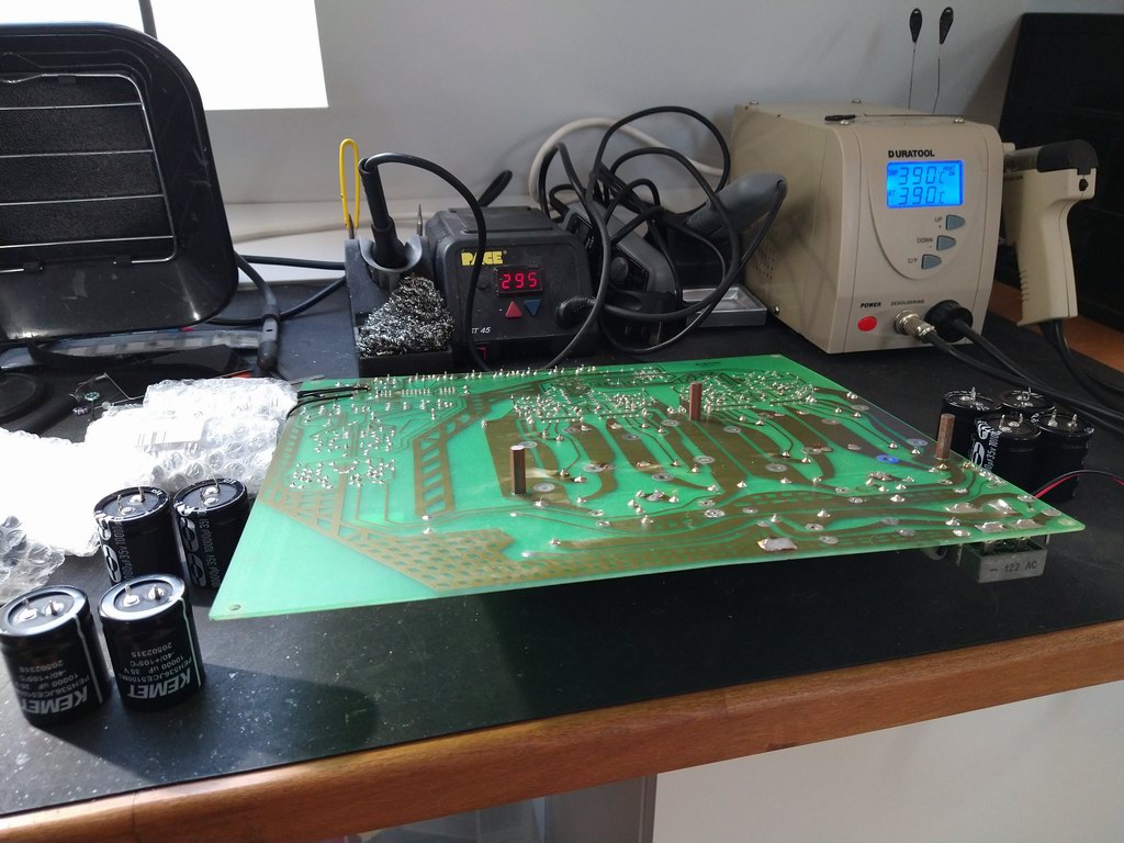
I also remembered that I was going to re-build the preamp stage which was a bit of a crazy design IMO but never got around to it. Well, now's the time. But first things first - I've got a full set of 105C 10,000U's to swap-in. The originals looked OK but they're just so old (and only rated for 85C which is a laugh in this Amp).
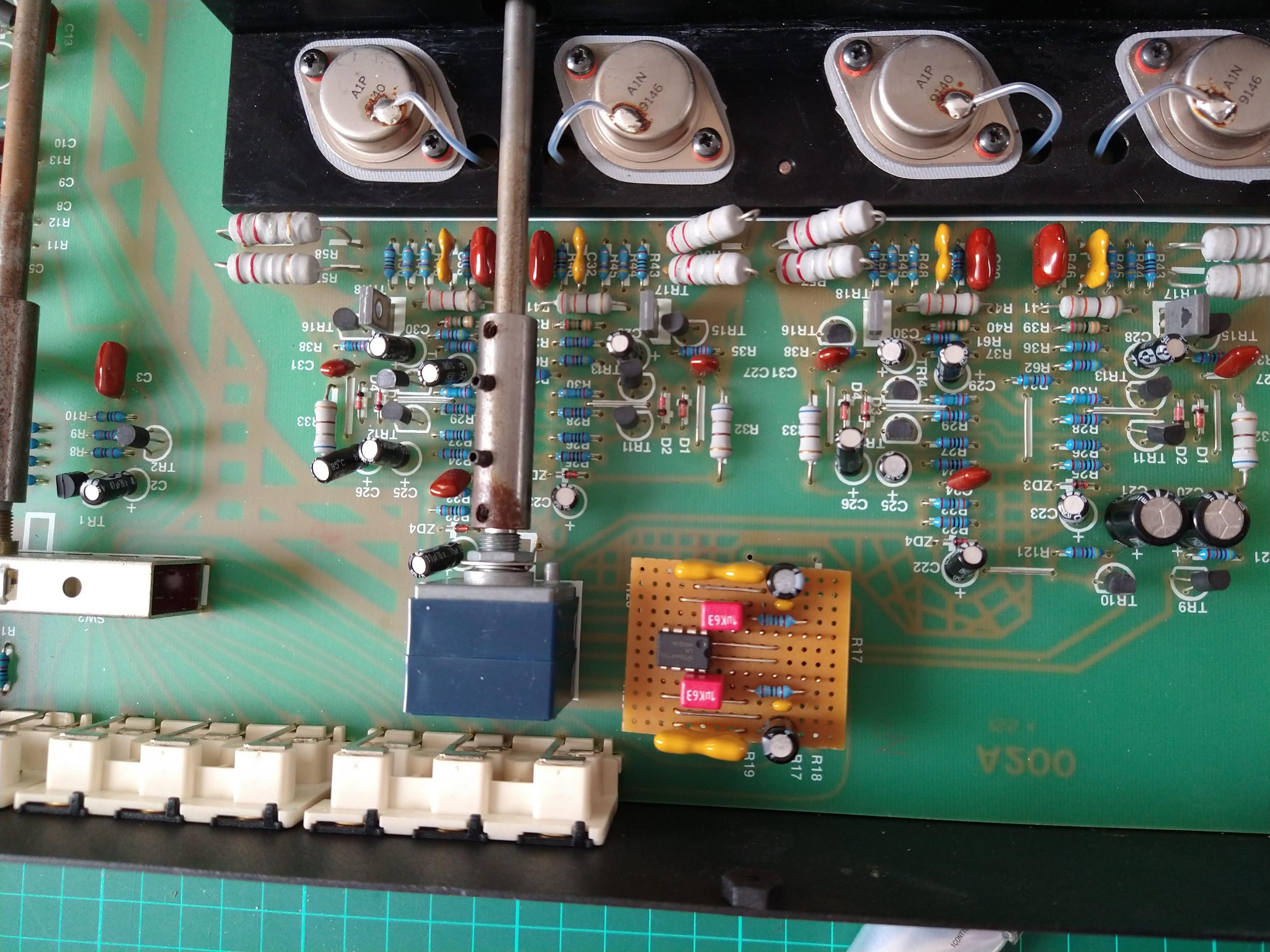
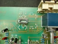
So here's the rusty article getting new caps:
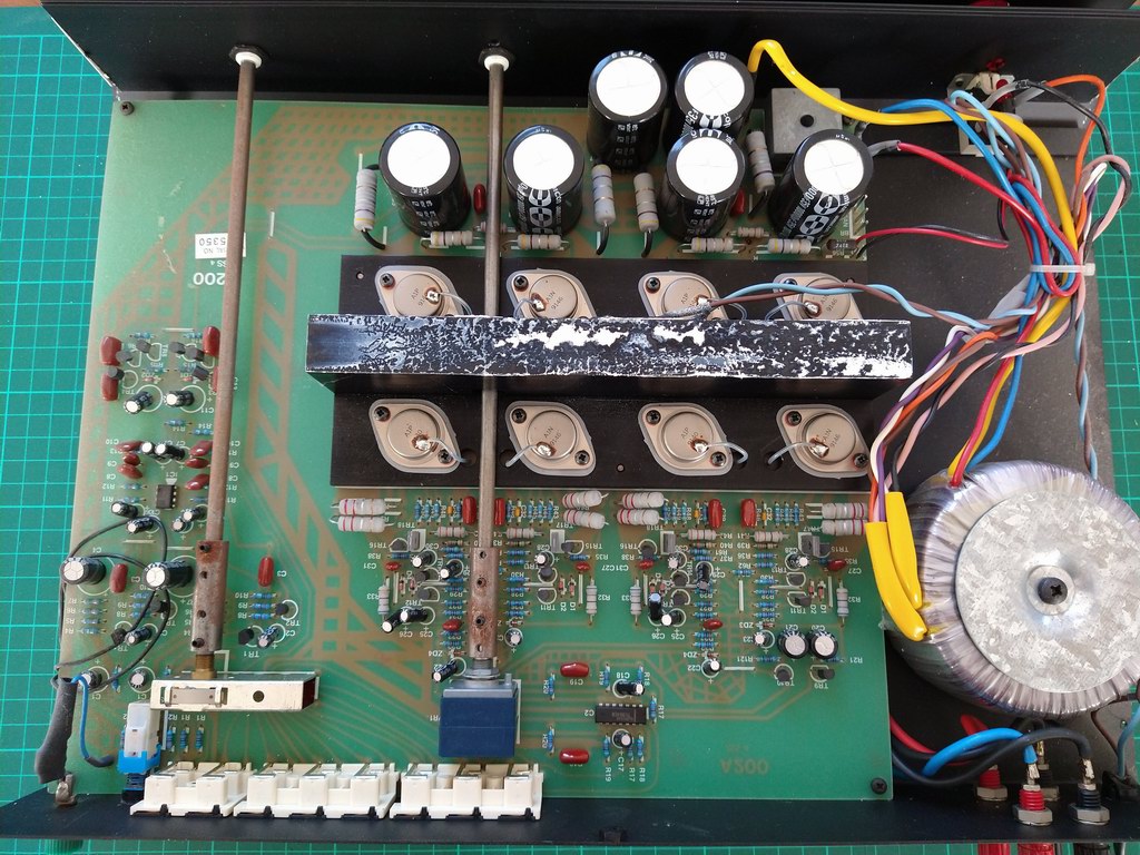
Funny how the PCB is labelled A200. I think this was a fan-cooled product that got re-engineered into a bigger case and called A120 to make it seem like a big brother to the A1. The circuit is very similar but has a higher supply voltage and separate reservoir capacitors for left and right channels in a CRC filter arrangement. The output transistors are also doubled-up to handle the higher dissipation.
One question I have about this thing... see the black wires looped over the phono section bottom left in the first photo? They loop round to the underside and basically parallel-up with two short tracks coming from the MC/MM switch. They don't actually provide a circuit, they're just little "loop antennae". This just looks so random. Anyone got a clue what the story is here?
Anyway, as for my next job I'm going to bypass the entire preamp stage and feed the signal directly into the power stage just to see if there's enough gain to be usable with a CD input.
I'm familiar with the A1 mods described at www.markhennessy.co.uk but the pot position at the back of the A120 makes his approach less attractive. Instead, if I do need some gain, I plan to remove all the parts associated with the original quad op-amp and link the inputs/power/outputs onto a DIL socket inserted into the same footprint. Then I can plug-in a custom daughter board with an improved design. I'm not bothered about cutting the odd track here and there, the original preamp design is never going to make a comeback
So I recently felt like some nostalgia and got my old MF amp out of storage. But did it ever make some awful crackling noises - I then remembered why I stored it (probably 20 years or more ago!).I also remembered that I was going to re-build the preamp stage which was a bit of a crazy design IMO but never got around to it. Well, now's the time. But first things first - I've got a full set of 105C 10,000U's to swap-in. The originals looked OK but they're just so old (and only rated for 85C which is a laugh in this Amp).
So here's the rusty article getting new caps:
Funny how the PCB is labelled A200. I think this was a fan-cooled product that got re-engineered into a bigger case and called A120 to make it seem like a big brother to the A1. The circuit is very similar but has a higher supply voltage and separate reservoir capacitors for left and right channels in a CRC filter arrangement. The output transistors are also doubled-up to handle the higher dissipation.
One question I have about this thing... see the black wires looped over the phono section bottom left in the first photo? They loop round to the underside and basically parallel-up with two short tracks coming from the MC/MM switch. They don't actually provide a circuit, they're just little "loop antennae". This just looks so random. Anyone got a clue what the story is here?
Anyway, as for my next job I'm going to bypass the entire preamp stage and feed the signal directly into the power stage just to see if there's enough gain to be usable with a CD input.
I'm familiar with the A1 mods described at www.markhennessy.co.uk but the pot position at the back of the A120 makes his approach less attractive. Instead, if I do need some gain, I plan to remove all the parts associated with the original quad op-amp and link the inputs/power/outputs onto a DIL socket inserted into the same footprint. Then I can plug-in a custom daughter board with an improved design. I'm not bothered about cutting the odd track here and there, the original preamp design is never going to make a comeback
Attachments

Hi NickUK, I hadn't even come across the A220 before. The official Musical Fidelity timeline isn't much use. There has to be a better reference out there.
So I powered-up the modified Amplifier to do some tests (quickly powering down before the transistors get hot). I have the input selection directly feeding the original 50K volume pot track with ground at the other end. With the wiper at full volume position, a 2VRMS sine is just beginning to clip. Backing-off the level I can see that the power amp has a voltage gain of 11.14 or around 21bB.

(Magenta trace is amplifier output just staring to clip)
So actually, for typical CD player source levels of around 2VRMS there maybe enough gain here already. However, the input impedance is obviously dependent on the pot setting so it would seem sensible to at least buffer the input with an op-amp. I think a gain of 2 will be plenty.
So I powered-up the modified Amplifier to do some tests (quickly powering down before the transistors get hot). I have the input selection directly feeding the original 50K volume pot track with ground at the other end. With the wiper at full volume position, a 2VRMS sine is just beginning to clip. Backing-off the level I can see that the power amp has a voltage gain of 11.14 or around 21bB.
(Magenta trace is amplifier output just staring to clip)
So actually, for typical CD player source levels of around 2VRMS there maybe enough gain here already. However, the input impedance is obviously dependent on the pot setting so it would seem sensible to at least buffer the input with an op-amp. I think a gain of 2 will be plenty.
hi Iceled, im working on the exactly same model as yrs (MF A120) and i plan to actually modify the integrated A120 into a 2 channel power amp. i have already built a separate preamp unit for this purpose and can plug the pre outs RCA into the A120 via the CD in.
would be pleased to have yr input on modifying the A120 into a power amp unit. things which i would need to omit would be the whole pre amp section and maybe even the volume control as the preamp does that. would need yr help in identifying which point to tap in the signal from pre amp into the motherboard.
after this mod, i foresee that it would look like the M50 but with 2 channels.
cheers
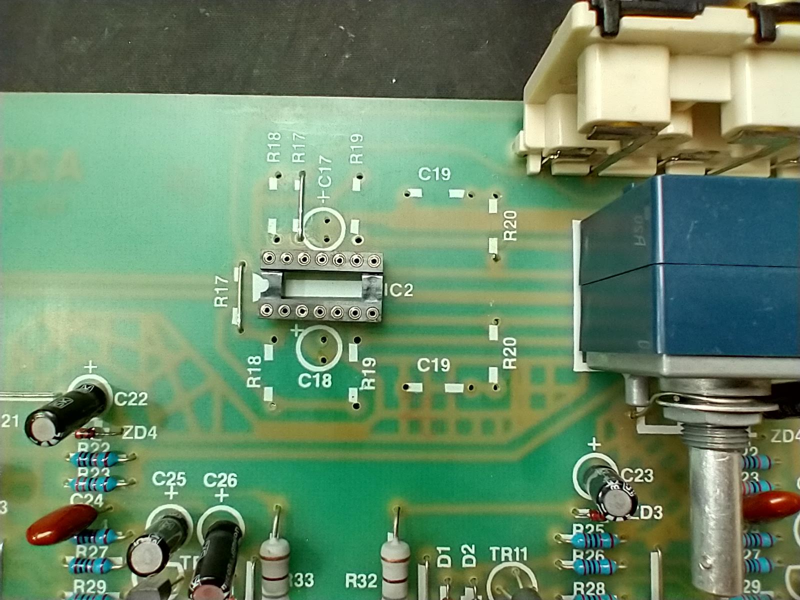
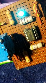
Hi, in the end I desoldered all the parts around the TL084 based preamp and fitted a 14-pin DIL socket in its place:
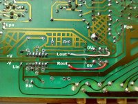
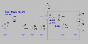
Into that I plugged my own design for a preamp built on stripboard:
The relevant signals were as shown here:
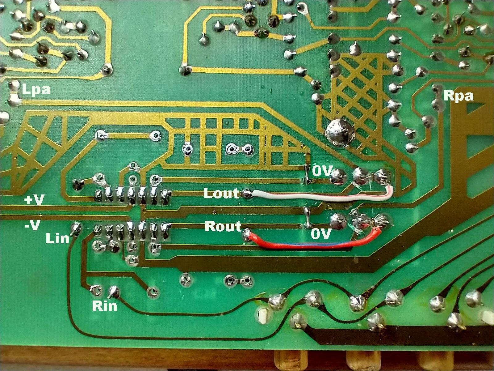
I decide to keep the original ALPS 50K pot with a bit of hackery to swap the connections so the tracks span preamp out and 0V, with the wiper feeding the PA stages. It gives me a much more comfortable gain control with my preferred listening level at positioned 12 O-clock.
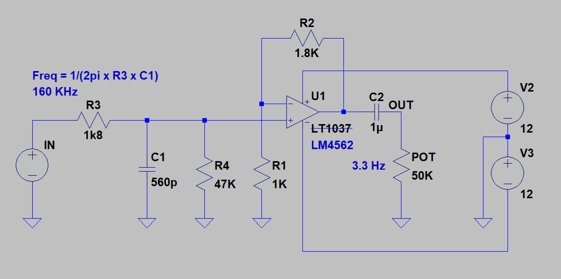
My simple preamp is based on the LM4562 and provides a voltage gain of 2.8
Nothing fancy but much better than the original IMO. AC coupling eliminates the dreaded pot crackle and the OPAMP is a bit of an improvement on the old TL084!
Into that I plugged my own design for a preamp built on stripboard:
The relevant signals were as shown here:
I decide to keep the original ALPS 50K pot with a bit of hackery to swap the connections so the tracks span preamp out and 0V, with the wiper feeding the PA stages. It gives me a much more comfortable gain control with my preferred listening level at positioned 12 O-clock.
My simple preamp is based on the LM4562 and provides a voltage gain of 2.8
Nothing fancy but much better than the original IMO. AC coupling eliminates the dreaded pot crackle and the OPAMP is a bit of an improvement on the old TL084!
Attachments

I expect we both appreciate the same cost/performance benefits of the LM4562
If you want to keep your preamp outside the chassis then all you need to do is remove both R17's and link Lin/Rin to Lpa/Rpa (as I labelled them on the photo of the track side) - but you need to cut the original tracks that ran to Lpa/Rpa (between the R22/R23 junctions and the ALPS pot.
You could remove all the other parts I've shown in addition to R17 but there's no need. Are you retaining the original case? The Lin/Rin tracks are post input selector so you will have to leave the selector in the right place. Of course you could also plug in a CD player or other direct source and listen without any preamp. Tape 1&2 have the shortest input path - I would use one of those for an external preamp and keep the CD input for preamp-less monitoring fun!
You could also keep the volume pot as a potential divider as I have done by hacking the PCB and linking Lin/Rin to Lout/Rout... but I get the feeling you plan to ditch the MF metalwork altogether. I think that would be a shame as I still get a kick out of the 90's looks
Frankly I'm also chuffed to bits with the sound of this thing now the horrid front-end is history. The volume control was always too aggressive as well as being in a DC path. These amps were always going to go 'crackly' eventually.
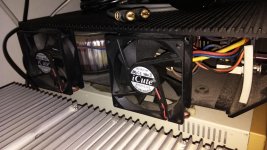
Would be retaining the MF metalwork with some modification to both the side panels to have 2 cooling fans each side.
If the preamp signal from outside were to be fed directly to Lpa & Rpa points, would there be any impedance matching issues?... this was the reason i asked if another LM4562 needs to be in place (maybe unity gain) just before Lpa & Rpa.
If the preamp signal from outside were to be fed directly to Lpa & Rpa points, would there be any impedance matching issues?... this was the reason i asked if another LM4562 needs to be in place (maybe unity gain) just before Lpa & Rpa.
Attachments
activex190, puginfo, this schematic for the A200 should answer both your questions:
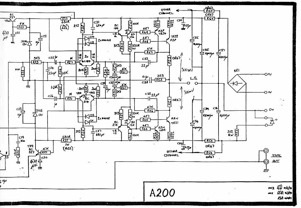
I found the above image @audiomaniacy.pl
IMO the PA input impedance shouldn't create any issues for the preamp cct I used although R22 (100K to ground) will slightly alter the taper of the log pot as I have used it - but I think it bends it in a good direction. It could of course be dispensed with altogether.
Attachments
- Home
- Amplifiers
- Solid State
- Musical Fidelity A120 modification