I my spare time I have been looking up all of the replacement caps for my A-77X. Being 36 years old, I though it might be time to do this. It's been on my work bench for the better part of this year cranking out the tunes while I'm in my shop(just my basement where a man can hide with his stuff.).
So, about a week ago I turned the 77 on and had just started playing some music. The audio dipped in volume, than just stopped and I noticed a wisp of smoke coming up from the Voltage Amplifier Assembly. I had been standing right in front of the amp when this happened and saw the smoke and I'm fairly certain it was coming from a particular transistor(although I can't be certain as the board is inverted) . When I had a closer look, I noticed that the solder joints for this one was loose and ringed.
I obtained a replacement 2SA1145, removed the old one and soldered the new one in.
Two of the fuses had blown, so I just replaced them (240V Fast 3.0A ). I turned the Amp on, it lit up but I did not hear the usual relay click. So, I turned the amp off, waited a minute or two and turned it back on. This time two of the fuses blew immediately. I have not turned it on since. I'm guessing the smoke didn't come from the transistor. On another message board, I have been getting some good pointers on replacement transistors and substitutions if it comes to that. But having replaced one and testing another, I'm not sure it was either of them as they both tested good as far as I can tell.
So, gentlemen, where to start? I don't have all of the testing gear - all I have is a standard commodity multi-meter and I'm building a dim bulb tester.
Is this something I can start into or perhaps I should hand it over to a pro?
Any help would be greatly appreciated. I consider it an old friend.
So, about a week ago I turned the 77 on and had just started playing some music. The audio dipped in volume, than just stopped and I noticed a wisp of smoke coming up from the Voltage Amplifier Assembly. I had been standing right in front of the amp when this happened and saw the smoke and I'm fairly certain it was coming from a particular transistor(although I can't be certain as the board is inverted) . When I had a closer look, I noticed that the solder joints for this one was loose and ringed.
An externally hosted image should be here but it was not working when we last tested it.
I obtained a replacement 2SA1145, removed the old one and soldered the new one in.
Two of the fuses had blown, so I just replaced them (240V Fast 3.0A ). I turned the Amp on, it lit up but I did not hear the usual relay click. So, I turned the amp off, waited a minute or two and turned it back on. This time two of the fuses blew immediately. I have not turned it on since. I'm guessing the smoke didn't come from the transistor. On another message board, I have been getting some good pointers on replacement transistors and substitutions if it comes to that. But having replaced one and testing another, I'm not sure it was either of them as they both tested good as far as I can tell.
So, gentlemen, where to start? I don't have all of the testing gear - all I have is a standard commodity multi-meter and I'm building a dim bulb tester.
Is this something I can start into or perhaps I should hand it over to a pro?
Any help would be greatly appreciated. I consider it an old friend.
Last edited:
About 35 years old.
Pioneer A-77X Stereo Integrated Amplifier Manual | HiFi Engine
Pioneer A-77X Stereo Integrated Amplifier Manual | HiFi Engine
Before I take this thing to somebody that can actually fix it, I did a bit more poking around. Specifically, the power transistors on the right and left output assemblys (GWH-172 and GWH-173). I now have a decent DMM and tested all 8 of the transistors (4 - 2SC2579 and 4-2SA1104). There are two of each on either side.
Both assemblies are nearly identical as far as I can tell.

Yes, I did test them all "in-circuit". I have read and understand the posts(stickies) above about testing transistors....
I did not expect the see very different results for both sides:
Hope the following makes sense - here are the results of the tests.
2SC2579 Left Chan 1
BIAS RevBIAS
B-E .543 B-E .681
B-C .538 B-C Inf
*C-E 1.7 C-E .954
2SC2579 Left Chan 2
BIAS RevBIAS
B-E .542 B-E .682
B-C .536 B-C Inf
*C-E 1.7.. C-E .954
2SA1104 Left Chan 1
L1
BIASED RevBIAS
B-E .648 B-E .580
B-C Inf B-C .578
C-E .969 C-E Inf
2SA1104 Left Chan 2
BIASED RevBIAS
B-E .648 B-E .580
B-C Inf B-C .578
C-E .969 C-E Inf
RIGHT CHANNEL:
2SC2579 #1
BIAS RevBIAS
B-E .125 B-E .125
B-C .125 B-C .125
C-E .001 C-E .001
2SC2579 #2
BIAS RevBIAS
B-E .127 B-E .128
B-C .127 B-C .128
C-E .001 C-E .001
2SA1104 #1
BIAS RevBIAS
B-E .003 B-E .003
B-C .003 B-C .003
C-E .001 C-E .001
2SA1104 #2
BIAS RevBIAS
B-E .016 B-E .016
B-C .016 B-C .016
C-E .001 C-E .001
I would have thought I'd see similar results on the right side as the left - even giving that I am testing in-circuit.
Thoughts?????
Both assemblies are nearly identical as far as I can tell.
Yes, I did test them all "in-circuit". I have read and understand the posts(stickies) above about testing transistors....
I did not expect the see very different results for both sides:
Hope the following makes sense - here are the results of the tests.
2SC2579 Left Chan 1
BIAS RevBIAS
B-E .543 B-E .681
B-C .538 B-C Inf
*C-E 1.7 C-E .954
2SC2579 Left Chan 2
BIAS RevBIAS
B-E .542 B-E .682
B-C .536 B-C Inf
*C-E 1.7.. C-E .954
2SA1104 Left Chan 1
L1
BIASED RevBIAS
B-E .648 B-E .580
B-C Inf B-C .578
C-E .969 C-E Inf
2SA1104 Left Chan 2
BIASED RevBIAS
B-E .648 B-E .580
B-C Inf B-C .578
C-E .969 C-E Inf
RIGHT CHANNEL:
2SC2579 #1
BIAS RevBIAS
B-E .125 B-E .125
B-C .125 B-C .125
C-E .001 C-E .001
2SC2579 #2
BIAS RevBIAS
B-E .127 B-E .128
B-C .127 B-C .128
C-E .001 C-E .001
2SA1104 #1
BIAS RevBIAS
B-E .003 B-E .003
B-C .003 B-C .003
C-E .001 C-E .001
2SA1104 #2
BIAS RevBIAS
B-E .016 B-E .016
B-C .016 B-C .016
C-E .001 C-E .001
I would have thought I'd see similar results on the right side as the left - even giving that I am testing in-circuit.
Thoughts?????
It does...
@ItsGarand:
You can easily desolder the right channel output transistors' legs from the PCB - use Soldapullt. Then, lift the legs slightly to ensure they are not making any contacts with the PCB.
Then repeat the test - that will tell you if the output transistors are shorted, or there's a fault somewhere on the PCB.
Edit: you'll most likely find that the output transistors are shorted AND there are semiconductors (diodes/driver transistors) shorted on the PCB as well.
Last edited:
At least one NPN and one PNP transistor are shorted and a very good chance that all of them are shorted. The reality is that fuses are rarely fast enough to save transistors.
As a warning, output transistors don't just fail. Something pushed them outside of their safe operating area, and you're going to have to figure out what that was before you replace them.
Edit: There is a very good chance that the drivers are also blown.
As a warning, output transistors don't just fail. Something pushed them outside of their safe operating area, and you're going to have to figure out what that was before you replace them.
Edit: There is a very good chance that the drivers are also blown.
Don't just change blown components before you find the real course.
This 35 years old gear needs a thorough check on every component.
check for bad solder joints,
resistors, short, open or value changed,
transistors leakage or bad,
capacitors leakage or bad--better change all caps,
diodes, zener diodes....the bias ic..
Time, patience is needed with care.
This 35 years old gear needs a thorough check on every component.
check for bad solder joints,
resistors, short, open or value changed,
transistors leakage or bad,
capacitors leakage or bad--better change all caps,
diodes, zener diodes....the bias ic..
Time, patience is needed with care.
At least one NPN and one PNP transistor are shorted and a very good chance that all of them are shorted. The reality is that fuses are rarely fast enough to save transistors.
As a warning, output transistors don't just fail. Something pushed them outside of their safe operating area, and you're going to have to figure out what that was before you replace them.
Edit: There is a very good chance that the drivers are also blown.
Sorry, bit of a noob, but not completely ignorant, just don't know some of the vernacular yet...
Can you explain the "drivers" Thanks!
Drivers are the transistors before those big output transistors... they are the ones that 'drive' them.
Use a bulb tester (60 or 100 watt filament bulb in series with the mains) ... never apply full mains to a faulty amp as it is asking for trouble. The bulb will prevent major component failures if anything is wrong.
Use a bulb tester (60 or 100 watt filament bulb in series with the mains) ... never apply full mains to a faulty amp as it is asking for trouble. The bulb will prevent major component failures if anything is wrong.
Drivers are the transistors before those big output transistors... they are the ones that 'drive' them.
Use a bulb tester (60 or 100 watt filament bulb in series with the mains) ... never apply full mains to a faulty amp as it is asking for trouble. The bulb will prevent major component failures if anything is wrong.
Yes. I'm in the process of building a dim-bulb tester. Since the 77x is capable of 100 Watts/Chan, will a single 100 watt bulb do?
You worked considerable time to destroy an amp which supposedly was in good condition
before. I am afraid it is useles to put more effort in it and buy expensive replacement parts..
Well, no. This Amp has seen a LOT of use over the last 30+ years and was definitively showing it's age. lamps were burned out and I had to take the front panel off to clean all of the contacts with deoxit just to get the left channel from dropping out. Aside from that, all I have done is study the schematics and compile a list of replacement caps.
Also, the Voltage Amplifier Assembly has two very dark spots (left and right channel) where two 3.3K and 2 zener diodes sit and the solder connections there are ringed and prone to failure. I have ordered and received replacements for those but have yet to do anything with them as the amp was still working.
I had cleaned it up well over a month ago and replaced the lamps - I have been using it ever since. One day I turned it on, it sounded funny and saw a small wisp of smoke come up from the (I believe the Voltage Amplifier Assembly ). I turned if off immediately. My only mistake here was replacing the fuses and turning it back on. Live and learn.
It is now a project. And I intend on learning as I go.
Last edited:
You worked considerable time to destroy an amp which supposedly was in good condition
before. I am afraid it is useless to put more effort in it and buy expensive replacement parts..
It very likely isn't the OP's fault. Yes, one channel of that amp is pretty well blown up from what it looks like, and he/she/other will need to replace quite a bit of silicon to get it back up and running. There is a good chance that the outputs were shorted even before he replaced the fuses.
The cost to rebuild this amp, assuming labor is free, won't be unreasonable. There aren't very many output devices.
There's always a reason for blown outputs, but often as not it's some other failure that leads to shorted outputs. More than a few times, I've seen cases where the bias spreader (or some other part of the thermal compensation scheme) opens, turning the output stage on hard.
I've watched a few amps do it before. Previous service can cause it, but so can a cracked solder joint, manufacturing defects, corrosion, etc. In bad designs, a failed bias pot can cause this. Why anyone would be stupid enough to design an amp such that a pot wiper going open leads to shorted outputs I can't imagine, but it's not unheard of.
I've watched a few amps do it before. Previous service can cause it, but so can a cracked solder joint, manufacturing defects, corrosion, etc. In bad designs, a failed bias pot can cause this. Why anyone would be stupid enough to design an amp such that a pot wiper going open leads to shorted outputs I can't imagine, but it's not unheard of.
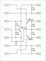
@ItsGarand:
That amp uses the infamous DIL14 IC: PA0016. It can not be sourced easily, and many listed on e-bay are fakes.... You may have to rebuild it if it's faulty - see attached.
Interesting. How would even know if that is bad?
By understanding the schematics of both, the IC ("internal" schematics, as I posted previously), and the amplifier schematics. I suppose there are two ways about it: you either use this amp as a testbed (for learning/experimenting), or - you give it to a good electronics technician/ engineer who could get it going for you.
If the first option seems viable to you, I suggest you start with a simple BJT amplifier circuit, and what voltages you'd expect to see if it is used as an amplifier. Some understanding of the current runs around the same circuit will be required, as well as the proper biasing to get that BJT to actually amplify voltage or current. You should also know how the typical NPN and PNP BJT's measure between 3 pins, in all "directions" - with an ohm-meter, and with a diode tester. For this, you'll need to have some idea of a semiconductor BJT construction... Then you can move to simple 2, or 3-gain stage designs.
Good luck.
Oh yes, I think it's a foregone conclusion that this amp will be going to a competent repair shop (there are a couple of good ones in the Baltimore-DC area) as I won't sacrifice it for simply a learning exercise. However, since I am the curious type and somewhat eager to lean about electronics (have always had an interest sine I grew up watching my dad put together his amateur radio gear - Heathkit), I though I'd take the opportunity to read the schematics and follow backwards from the power transistors to see if I could find anything else that went bad. Perhaps I won't since testing transistors and capacitor in circuit is either problematic or near impossible. I'd rather not pull components off board if somebody else is going to rehab the amp.
Now, if I was convinced that it was just those 4 power transistors and I could locate original replacement parts, I'd replace them myself.
Oh and I have become familiar with testing transistors - all four power transistors in the right channel output are shot.
Thanks for the reply!
Now, if I was convinced that it was just those 4 power transistors and I could locate original replacement parts, I'd replace them myself.
Oh and I have become familiar with testing transistors - all four power transistors in the right channel output are shot.
Thanks for the reply!
- Home
- Amplifiers
- Solid State
- Pioneer A-77X trouble shooting help needed.