This is a companion amplifier to the synthesised sinewave generator, for driving low-voltage 2-phase motors.
There are many amplifier modules available, but due to the output voltage swing required, these will typically have quite a high power rating as they are intended to drive low-impedance loads, which is not needed for this application.
An Analog Devices application note shows a high-voltage amplifier which seemed promising for this application, using an op-amp with supply current sensing and a potential divider on the op-amp output to provide both a current boost and allow the high voltage rails:

A 2-channel amplifier suitable for a low-power synchronous motor based on this concept has been produced (non-inverting, zener references), using mostly non-critical parts. The TL071 op-amp proved suitable, with the only critical component being C1 for the stability of the current feedback loop:

With C1 of 1nF, step responses at 70Hz (left) and 5kHz (right) are good:


A PCB is available, Gerbers and build guide are attached to this post.

Full details also on my GitHub
There are many amplifier modules available, but due to the output voltage swing required, these will typically have quite a high power rating as they are intended to drive low-impedance loads, which is not needed for this application.
An Analog Devices application note shows a high-voltage amplifier which seemed promising for this application, using an op-amp with supply current sensing and a potential divider on the op-amp output to provide both a current boost and allow the high voltage rails:
A 2-channel amplifier suitable for a low-power synchronous motor based on this concept has been produced (non-inverting, zener references), using mostly non-critical parts. The TL071 op-amp proved suitable, with the only critical component being C1 for the stability of the current feedback loop:
With C1 of 1nF, step responses at 70Hz (left) and 5kHz (right) are good:
A PCB is available, Gerbers and build guide are attached to this post.
Full details also on my GitHub
Attachments
Last edited:
Simple? Perhaps 30 years ago. With chip amps or readily available class D modules this is unnecessarily complicated.
Where's the fun if you don't do it the discrete parts way? 😉
FWIW, Elektor published a few versions of audio output stages driven from the rails of an opamp - dating from the 1980s, I think. The attached schematic is the simplest Mosfet version but BJT and better versions turned up in their circuit pages occasionally too. Google will find them without much effort.
FWIW, Elektor published a few versions of audio output stages driven from the rails of an opamp - dating from the 1980s, I think. The attached schematic is the simplest Mosfet version but BJT and better versions turned up in their circuit pages occasionally too. Google will find them without much effort.
Attachments
Thanks Ian, exactly, it's nice to experiment with a neat idea, there's rarely much new under the sun!
In the PDF attachment is an example therefore.Simple? Perhaps 30 years ago. With chip amps or readily available class D modules this is unnecessarily complicated.
What I don't understand is the adjustment procedure of the sine wave oscillator.
1) Tr2 and Tr3 are for pre adjustment for 33 rpm speed in such kind, that P2A/B (outdoor adjustment therefore) provide the correct speed in the middle position - but how get I best synchronisation of P2A and P2B ?
2) What is the aim of TR4 ?
Only the function of Tr1 I understand - it is a level adjust for one motor winding half - the adjust is perform in such kind, that a minimum of mech. hum level is present.
Thank you for an advice.
Attachments
In the PDF attachment is an example therefore.
A very similar circuit has been partially analysed by Rod Elliot (state variable filter). My head hurts from the abundance of pots 🙂
Tr4 is perhaps to set the gain for best distortion.
https://sound-au.com/articles/sinewave.htm
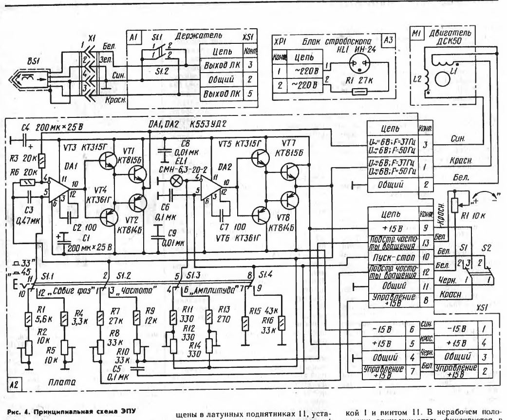
This is practically a carbon copy of Thorens TD125 mk2.
Hi richb,
This looks to be just what I'm looking for. On the other hand, there are some things I do not understand. Especially when I was reading you can supply it with a single 24V AC transformer. I do not understand how, without a middle tap and I think voltage is low too if you create a virtual ground. From 24V AC you may get about 33V DC, lets say +15V and -15V. From that, we could get about 10V eff I think.
I guess I'm wrong somewhere, but I just do not understand how it works, please help. Would you be willing to share design files? I would put a full wave rectifier on and tapped transformer connection.
Also, I do not understand the HV board. I use transformert to drive 110V motors after LM3886 modules, but what are the additional circuits are doing on the board I could not find out. Can you please explain that?
Thanks a lot!!!!
JG
Hi JG, the circuitry in the top left of the schematic, shown below, is a pair of half-wave rectifiers, which will give approx. +-Vpeak of the input AC on VPOS and VNEG. These then becomes the 'DC rails' for the output AC sinewave. Because of the small voltage drop of the diodes, the cycle-cycle droop due to the discharging of the capacitors under load, and the output waveform having to have a small voltage margin to the rails, the maximum output AC voltage will be a little less than the input AC voltage. From memory, with the original Rega 24v 0.1A transformer, I think I managed around 18v RMS output, which seemed adequate to drive the 24v TT motor. Using a higher VA rated 24v AC supply I got a bit closer still, and my curent implementation uses approx +-40v DC rails from a repurposed amplifier chassis which then allows the full 24v AC output with this design.

The 'spinamp_HV' is a companion board with transformers which will allow the generation of 110v AC for the motor, the additional circuitry enables the transformer output to be included in the amplifier feedback loop, thus giving good control of the output amplitude and waveshape.
The schematics, BOM and PCB Gerbers are included above, so should allow you to reproduce either system as desired.
Hi richb,
Thanks! I understand now mostly. Why don't you use a tapped transformer and full wave rectifier? It would be much easier to reduce ripple. Is that because you had available 24V single transformer? The reason why I wanted to ask for the design files, I would just put on a Graetz, that is it.
On the HV board, I know why transformers. I've used also to run Airpax/Premotec/Philips 110V sycn motors, but what is the additional circuit is doing? I mean, I see you connect the amplifier to H7, H9 and after ther transformes, the motor goes to P1. But, what is the other circuits are doing, I can not recognize.
The R1-R5, C1-C3 looks like a feedback network, or similar, where is J1/H1 and J2/H10 or H2, H8 going to? Also, what is the Z1, Q1... rectifier is for?
Thanks a lot!
JG
The half-wave rectifier is included as it allowed the use of the transformer that originally directly connected to the motor. However, I have an as yet unpublished v2 of the spinamp PCB which has provision for a full wave rectifier too.
Don't forget that the HV board is used in conjunction with the first board, to give the effect described above.
I'm away today, I'll get the details of the updated PCB added soon after I'm back.
Don't forget that the HV board is used in conjunction with the first board, to give the effect described above.
I'm away today, I'll get the details of the updated PCB added soon after I'm back.
JG, I've just remembered, there is some further explanation of the HV board here on the supaspin thread. I've also uploaded the v2.1 Gerbers in the first post (but haven't yet updated the build gide for it)
- Home
- Amplifiers
- Solid State
- simple amplifier for turntable synchronous motor drive