Hello everyone.")
This is the first thread I have opened here with the aim to share my experiences with you and to broaden my knowledge about electronics from possible replies.
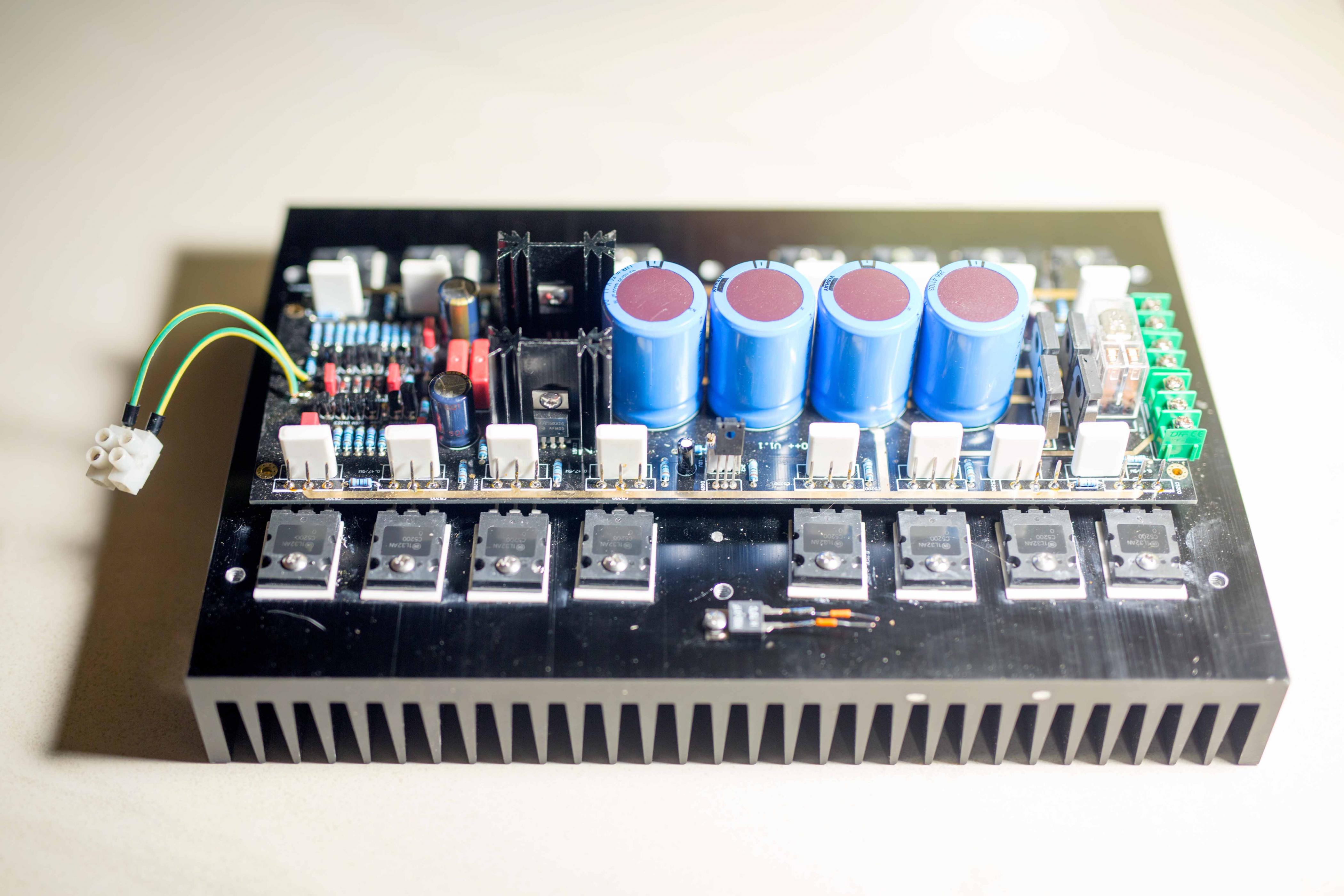
Over the 2020/2021 winter I have built an amplifier based on A60+ boards from eBay and was quite satisfied with the result: an amplifier sounds great, is relatively easy to build and involves everything what is needed to complete the project: power supply and effective speaker protection.
Below is a photo of one channel of the amplifier.
The amplifier comes in two different versions:
A60, smaller, with 3 output pairs of transistors
A60+, larger, with 8 pairs of output transistors.
There are variety of possible versions: with different output transistors
MJL3281A/MJL1302A
2SA1943/2SC5200
It is also possible to purchase bare boards, partially stuffed boards, complete boards and also amplifiers in chassis.
In addition to this the board incorporates a solid power supply and effective speaker protection. You only have to add your heat sinks large enough, transformers, transistors and capacitors.
I have decided initially for a A60+ version without output transistors and without power supply capacitors.
I also have tested A60+ and it sounds splendid indeed. Someone else on internet said its sound is "golden" and has gone that far to state that it has "euphoric tone". He is right it really sounds extraordinary. Just read this review.
I have also done extensive measurements: it measures great. It is done right across the whole audio spectrum and beyond. I will repeat the measurements and make them soon public.
The sound was great so I have decided to spend a bit more of time and money on this project.
I have purchased two A60+ and three smaller A60. This will be my spring 2021 project.
Finally, some hints for these who decide to build this amplifier:
Only capacitors with diameter 35mm and 10mm lead spacing will fit into this board. Initially I was afraid that just 4X10.000uF per channel wouldn't be enough, but it works indeed very well.
Carefully with biasing – this is a wild beast and can quickly go incredibly hot.
Chose heat sinks large enough to have freedom to set higher bias.
This is the first thread I have opened here with the aim to share my experiences with you and to broaden my knowledge about electronics from possible replies.
Over the 2020/2021 winter I have built an amplifier based on A60+ boards from eBay and was quite satisfied with the result: an amplifier sounds great, is relatively easy to build and involves everything what is needed to complete the project: power supply and effective speaker protection.
Below is a photo of one channel of the amplifier.
The amplifier comes in two different versions:
A60, smaller, with 3 output pairs of transistors
A60+, larger, with 8 pairs of output transistors.
There are variety of possible versions: with different output transistors
MJL3281A/MJL1302A
2SA1943/2SC5200
It is also possible to purchase bare boards, partially stuffed boards, complete boards and also amplifiers in chassis.
In addition to this the board incorporates a solid power supply and effective speaker protection. You only have to add your heat sinks large enough, transformers, transistors and capacitors.
I have decided initially for a A60+ version without output transistors and without power supply capacitors.
I also have tested A60+ and it sounds splendid indeed. Someone else on internet said its sound is "golden" and has gone that far to state that it has "euphoric tone". He is right it really sounds extraordinary. Just read this review.
I have also done extensive measurements: it measures great. It is done right across the whole audio spectrum and beyond. I will repeat the measurements and make them soon public.
The sound was great so I have decided to spend a bit more of time and money on this project.
I have purchased two A60+ and three smaller A60. This will be my spring 2021 project.
Finally, some hints for these who decide to build this amplifier:
Only capacitors with diameter 35mm and 10mm lead spacing will fit into this board. Initially I was afraid that just 4X10.000uF per channel wouldn't be enough, but it works indeed very well.
Carefully with biasing – this is a wild beast and can quickly go incredibly hot.
Chose heat sinks large enough to have freedom to set higher bias.
Last edited:
Needing another large amp for bass duties i recently examined the Accuphase line up as the service manuals for many models are readily available. Moreover Accuphase are very open about their designs and publish nearly explicit circuits in their marketing literature 
Over the last 10-15 years Acc have switched onto CFB and their entire lineup is built following the same basic topology.
The lineup is also separated into "class A" and class AB designs. The "class A" generally run in class A up to around 1/3 of their nominal 8-ohm power. Which in many cases is not a lot. Obviously the class A power into 4 ohms is half that.
Also interesting is that the "class A" are all with mosfet outputs while the class AB are exclusively bipolar. Reading subjective impressions of the class A vs class AB designs i have a suspicion the reported differences are due to the bipolar/mosfet outputs in at least equal measure as the difference in bias.
A weird topological feature is the paralleling of the input stage, presumably to reduce noise. The higher up one gets along the lineup, the more paralleled input stages.
Which brings us to the Chinese clone. Being entirely bipolar it is obviously not a direct transplant of the Acc A60. The topology is very similar except for some unnecessary complications around the cascoded VAS but what is really surprising is the current gain structure. It seems obvious a bipolar output needs more current gain than a mosfet, but clearly not to the designers of this board. As a result the VAS is overloaded and distortion goes through the roof. The savings are minimal, just a pair of driver transistors.
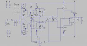
My conclusions are based on A60+ circuits found on seller's sites. As these were not very legible i made the effort to compare the drawings to the boards. Below is what i came up with.
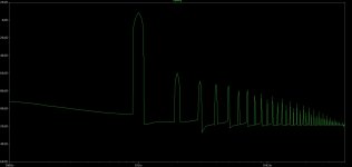
Distortion @1kHz/8ohms in simulation is around 0.04% even at low power. For comparison, a simulation of Acc P7100 which has a very similar topology but with sufficient current gain shows two orders of magnitude less distortion.
Cannot see a reason to recommend a design which appears to have been willfully hamstrung.
Over the last 10-15 years Acc have switched onto CFB and their entire lineup is built following the same basic topology.
The lineup is also separated into "class A" and class AB designs. The "class A" generally run in class A up to around 1/3 of their nominal 8-ohm power. Which in many cases is not a lot. Obviously the class A power into 4 ohms is half that.
Also interesting is that the "class A" are all with mosfet outputs while the class AB are exclusively bipolar. Reading subjective impressions of the class A vs class AB designs i have a suspicion the reported differences are due to the bipolar/mosfet outputs in at least equal measure as the difference in bias.
A weird topological feature is the paralleling of the input stage, presumably to reduce noise. The higher up one gets along the lineup, the more paralleled input stages.
Which brings us to the Chinese clone. Being entirely bipolar it is obviously not a direct transplant of the Acc A60. The topology is very similar except for some unnecessary complications around the cascoded VAS but what is really surprising is the current gain structure. It seems obvious a bipolar output needs more current gain than a mosfet, but clearly not to the designers of this board. As a result the VAS is overloaded and distortion goes through the roof. The savings are minimal, just a pair of driver transistors.
My conclusions are based on A60+ circuits found on seller's sites. As these were not very legible i made the effort to compare the drawings to the boards. Below is what i came up with.
Distortion @1kHz/8ohms in simulation is around 0.04% even at low power. For comparison, a simulation of Acc P7100 which has a very similar topology but with sufficient current gain shows two orders of magnitude less distortion.
Cannot see a reason to recommend a design which appears to have been willfully hamstrung.
Attachments
I see that something is catastrophically defective
While i don't mind a zero nfb amp with 0.1% distortion, a high NFB amp with 0.04% @1W and an ugly spectrum is not something i can stomach. It will take me relatively little effort to design a pcb for my use which is less defective. Admittedly, this is more work and expense than buying a Chinese board.
While i don't mind a zero nfb amp with 0.1% distortion, a high NFB amp with 0.04% @1W and an ugly spectrum is not something i can stomach. It will take me relatively little effort to design a pcb for my use which is less defective. Admittedly, this is more work and expense than buying a Chinese board.
Those skilled in the art know that simulation is just a starting point in evaluation, good tool to aid design but not the tool that can be used to evaluate and make definitive answers. This is true especially when there is no schematics whatsoever, no relevant data. Without schematics and real data you may just speculate.
I do not understand why should someone create a fake model? What is the real purpose of that? I do not believe that someone would fabricate results just for fun?
I will leave this as is because I want to evade unnecessary tensions where members should behave like friends, ready to help, not to destroy.
I am a successful scientist and an entrepreneur in another scientific area - chemistry. I wrote A-class papers published in worlds the best magazines and have read many scientific and technical papers. I have never accoutered something similar to what I have witnessed here in just few sentences.
I have kindly asked moderators to delete this entire thread because there is nothing here to be proud of. Quite the contrary.
Regards
I see that something is catastrophically defective
While i don't mind a zero nfb amp with 0.1% distortion, a high NFB amp with 0.04% @1W and an ugly spectrum is not something i can stomach. It will take me relatively little effort to design a pcb for my use which is less defective. Admittedly, this is more work and expense than buying a Chinese board.
Could you buy the clones and just mod them? Win-win situation
That's the word of real DIYer: If there is a problem, then solve it. But the problem our dear friend analog_SA is addressing doesn't exist.Could you buy the clones and just mod them? Win-win situation
Namely, there is no real schematics of this amplifier so his simulation is modestly speaking inaccurate, or should I say fabricated, fake. Just look at the schematics, below. That is all we have at the moment. So is it possible to simulate this and make so bold and final conclusions
So, let's go on and see the measurements. That is what counts.

Last edited:
Namely, there is no real schematics of this amplifier so his simulation is modestly speaking inaccurate, or should I say fabricated, fake.
I think i am going to limit my participation in your thread. Enjoy the golden sound.
My dear friend, I will miss very much you and your kind advices.I think i am going to limit my participation in your thread. Enjoy the golden sound.
That's the word of real DIYer: If there is a problem, then solve it. But the problem our dear friend analog_SA is addressing doesn't exist.
Namely, there is no real schematics of this amplifier so his simulation is modestly speaking inaccurate, or should I say fabricated, fake. Just look at the schematics, below. That is all we have at the moment. So is it possible to simulate this and make so bold and final conclusions
So, let's go on and see the measurements. That is what counts.
The schematic is the same as Analog_Sa draw, you just have more output pairs, it's a double EF if I remember well the original use output triple?
But of course, schematic of Accuphase A-60 has been published, but nobody claims that the A60+ is a clone, there is just a remote commercial statement in Chinglish "refer to" which could be understood as "inspired by". I don't know, I don't speak Chinglish. Therefore, in this case I have avoided even mentioning Acc...
Thus comparing these two amplifiers side-by-side is inadequate, especially if it is based on inaccurate reading of blurry and imprecise schematics, without clear identification of individual components and their values.
In such case it is much more appropriate to measure the response of the amplifier under consideration and evaluate it based on the measurements. Everything else is just speculation.
I have been professionally involved in experimental science and have spend a good half of my life measuring rather "invisible" abstract values. Similarly electronic circuits have own experimental methods which are much more adequate than simulations, especially these based based on assumed values.
That's what I wanted to say about this matter.

WOW Erlend, that's a beautiful piece of equipment. Well done!
As I can see you haven't cut corners with heat sinking. Yeah, larger is better and safer too. Who cares for money, life is too short for skimping.
Also, these extra capacitors will help indeed because I felt a bit insecure with these four pathetic 10.000uF capacitors. I also plan to invest more in that important department.
Erlend, I feel much better now and here in presence of sincere and dear friend.
By the way, 3 smaller bare boards with "just" three pairs are on the way, bit slowly because of the Chinese New Year holidays. One is for me and the other is for a friend from Croatia. If you don't mind I'd like to send the third to you - for soldering practice.
Cheers
Spot-on Walkalone,I remember that Accuphase A-60 uses audio vertical MOSFET 2SK3497/2SJ618, NOT bipolar as output. The driver stage is also audio vertical MOSFET 2SK2013/2SJ313.
The is only one similar point between your Accuphase clone and real A-60 that is both run as CFA topology.

There is also a version with 3 output pairs and yet direct comparison is impossible and unnecessary. Why should someone compare apples and oranges, except with aim to conclude that oranges are sour.
Furthermore, when using scientiffic tools (computer aided design tools) as analytical tool, one should adhere strictly to scientific methodology, which involves verification of the input data in the first place. Otherwise analysis is pseudo-scientific, just mimics, or should I say pretends to be a serious analysis. Using pathetically bogous data usually leads to profanisation of scientiffic tools. We used to say once upon a time: GIGO - garbage in - garbage out.
Thanks again for many your posts at this forum which I have read with a great deal of interest.
Last edited:
Recently I've heard someone saying "Amplifier that measures good can't sound bad". I am among those who agree with that.
So let's see first the bandwidth of this amplifier. For measurements I have used a board with 8 pairs of genuine 2SA1943/2SC5200. I have also used four 10.000uF/63V Vishay MAL205148103E3 capacitors. The rails were at +/-42,5 V.
For load I have used three 22R/100W resistors (Arcol HS100 22R J) in parallel.
I have warmed up the amplifier for 1 hour before taking measurements.
First I have determined that the amplifier has a ruler-straight frequency response over the entire audible range. Furthermore, the amplifier has -3dB roll-of at 340kHz.
At low frequencies there was no roll-of at all, just speaker protection turned the output off at 1,5Hz.
This can be considered as adequate bandwidth.
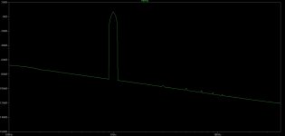
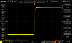
I have proceeded with square wave response analysis. It would be pointless to show a series of perfect rectangles indicating adequate square wave response within the entire audible range. Instead, the figure below shows just the initial part of the response to 50Hz square wave. The figure shows rise within 1.25uS followed by constant peak amplitude.

So let's see first the bandwidth of this amplifier. For measurements I have used a board with 8 pairs of genuine 2SA1943/2SC5200. I have also used four 10.000uF/63V Vishay MAL205148103E3 capacitors. The rails were at +/-42,5 V.
For load I have used three 22R/100W resistors (Arcol HS100 22R J) in parallel.
I have warmed up the amplifier for 1 hour before taking measurements.
First I have determined that the amplifier has a ruler-straight frequency response over the entire audible range. Furthermore, the amplifier has -3dB roll-of at 340kHz.
At low frequencies there was no roll-of at all, just speaker protection turned the output off at 1,5Hz.
This can be considered as adequate bandwidth.
I have proceeded with square wave response analysis. It would be pointless to show a series of perfect rectangles indicating adequate square wave response within the entire audible range. Instead, the figure below shows just the initial part of the response to 50Hz square wave. The figure shows rise within 1.25uS followed by constant peak amplitude.
Attachments
Last edited:
- Home
- Amplifiers
- Solid State
- A60(+) Amplifier. Build this?