Hi everyone
I just joined this forum, where I saw lots of interesting posts on amp with STK circuits repair.
I have 2 non-working Technics SU-V2 amps (link for service manual here : Technics manuals | Hifi Manuals Free: page 5) that I want to repair.
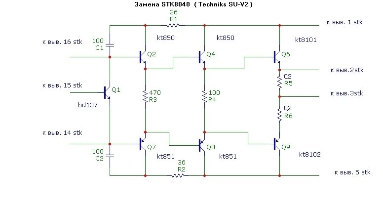
Both have faulty STK8040, so I intend to replace them wih discrete components such as those described in another thread of the forum.
But prior to that, I have to make sure the rest of the electronics is OK ... and I need help for that.
To start with, amp #1 : both STKs (IC301 and IC302) are dead, and so is tone controller op amp (IC303) => I removed those 3 circuits and tested all measurements points in the ”pre-STK" amp section (transistors Q301 to Q318 area) as mentioned on the schematics.
I found out some differences with nominal values : are voltages supposed to be the same as indicated on the schematics or does the removal of the 3 ICs have an impact on their values ? If so, which values should I expect ?
Thanks for your help
I just joined this forum, where I saw lots of interesting posts on amp with STK circuits repair.
I have 2 non-working Technics SU-V2 amps (link for service manual here : Technics manuals | Hifi Manuals Free: page 5) that I want to repair.
Both have faulty STK8040, so I intend to replace them wih discrete components such as those described in another thread of the forum.
But prior to that, I have to make sure the rest of the electronics is OK ... and I need help for that.
To start with, amp #1 : both STKs (IC301 and IC302) are dead, and so is tone controller op amp (IC303) => I removed those 3 circuits and tested all measurements points in the ”pre-STK" amp section (transistors Q301 to Q318 area) as mentioned on the schematics.
I found out some differences with nominal values : are voltages supposed to be the same as indicated on the schematics or does the removal of the 3 ICs have an impact on their values ? If so, which values should I expect ?
Thanks for your help
There is plenty of free space in the case to accommodate the power amplifier replacement board.
Technics SU-V2 - Le forum Audiovintage
Technics SU-V2A - 2
Feature - the tone control is included in the feedback circuit of the power amplifier.
Technics SU-V2 - Le forum Audiovintage
Technics SU-V2A - 2
Feature - the tone control is included in the feedback circuit of the power amplifier.
Last edited:
Goodmornig,
I'm new in this forum. I am keen on vintage elctronics, but I am not an expert.
Hope to write in the right section. Sorry for reviving a 2021 post.
Introduction: My SU-V2A has been repaired a couple of times by replacing the burned STK8040 with those IC ... fake IC I could find online. I opened them after burning and I could appreciate the main differences between the burned original and the non original. One stk 8040 is still working, just one channel. I tested it also in the other channel in order to check the electronics around the IC.
Repair with replacement of discrete components: I've dismounted the STK8040 ICS and the relative controlling electronics, hope not too much") (green and orange in the picture), and red dashed line in the schematic pictures.
(green and orange in the picture), and red dashed line in the schematic pictures.
 (The red hand written gnd indication is not meaning that the pin is GND, but my intention to connect it to gnd in order to have a try to manage with the protection circuit)
I'd like to implement the amplifier with a couple of Amplifier board like the following "Suqiya-nuovo tubo 2SC5200 2SA1943 Mono canale HIFI scheda amplificatore Audio 100W DC 35V C1-001" that needs the same potential powered by the amplifier supply:

Question: How may I improove the SU V2A with these kind of boards? where can I get the signal from the SUV2A preamplifier (including tone controller)? Is it correct having removed those components I mentioned above? ... may be the Q317 and Q318 should stay ...
My test: Giving power, I read the dual voltage both in the power and service lines. Signal in aux in order to look for the preamplified signal in the SUV2A to test with an axternal amplifier--> found signal just in C301 or C302. Signal NOT managed by the filters and tone control... . Trying to get the signal from pin 16/14 ... NOTHING.

I apologise for being so horribly long, and probabbly boring.
Hope to find someone interested in this challenge.
Many Thanks.
I'm new in this forum. I am keen on vintage elctronics, but I am not an expert.
Hope to write in the right section. Sorry for reviving a 2021 post.
Introduction: My SU-V2A has been repaired a couple of times by replacing the burned STK8040 with those IC ... fake IC I could find online. I opened them after burning and I could appreciate the main differences between the burned original and the non original. One stk 8040 is still working, just one channel. I tested it also in the other channel in order to check the electronics around the IC.
Repair with replacement of discrete components: I've dismounted the STK8040 ICS and the relative controlling electronics, hope not too much
(green and orange in the picture), and red dashed line in the schematic pictures.I'd like to implement the amplifier with a couple of Amplifier board like the following "Suqiya-nuovo tubo 2SC5200 2SA1943 Mono canale HIFI scheda amplificatore Audio 100W DC 35V C1-001" that needs the same potential powered by the amplifier supply:
Question: How may I improove the SU V2A with these kind of boards? where can I get the signal from the SUV2A preamplifier (including tone controller)? Is it correct having removed those components I mentioned above? ... may be the Q317 and Q318 should stay ...
My test: Giving power, I read the dual voltage both in the power and service lines. Signal in aux in order to look for the preamplified signal in the SUV2A to test with an axternal amplifier--> found signal just in C301 or C302. Signal NOT managed by the filters and tone control... . Trying to get the signal from pin 16/14 ... NOTHING.
I apologise for being so horribly long, and probabbly boring.
Hope to find someone interested in this challenge.
Many Thanks.