Hi everyone, and happy newyear 
Sorry if this has been discussed before, could not find anything on it.
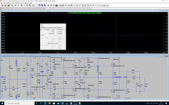
I have very much enjoyed dado's 200W CFA thread and downloaded the .asc file from post #1582 assuming it is the newest.
I did not have the IRFP240Ckst/IRFP240Ckst models handy, so instead I used the following models from Ian Hegglun.
*VDMOS with subthreshold (c) Ian Hegglun
.model IRFP240h VDMOS (Rg=17 Vto=4.0 Kp=6 Lambda=3m
+ Rs=40m Ksubthres=0.15 Mtriode=0.35 Rd=0.15
+ Bex=-2.3 Vtotc=-6m Tksubthres1=4m Trs1=3.5m Trd1=5m
+ Cgdmax=1.3n Cgdmin=10p a=0.35 Cgs=1.2n Cjo=1n
+ m=0.4 VJ=0.75 IS=10n N=1.5 Eg=1.1 Rb=10m Trb1=3m
+ Vds=200 Ron=0.15 Qg=45nC mfg=VishIH1907)
*VDMOS with subthreshold (c) Ian Hegglun
.model IRFP9240h VDMOS (pchan Rg=9 Vto=-3.76 Kp=9
+ Rs=64m Ksubthres=0.15 Mtriode=0.2 Rd=0.25 Lambda=4m
+ Bex=-2.3 Vtotc=+6m Tksubthres1=4m Trs1=3.5m Trd1=5m
+ Cgdmax=1.6n Cgdmin=30p a=0.5 Cgs=1.4n Cjo=1n
+ m=0.4 Vj=0.75 N=7 Is=10u Eg=3.15 Rb=50m Trb1=0
+ Vds=-200 Ron=0.5 Qg=44nC mfg=VishIH1907)
I then ran the bode plot as is, without changing anything else. It gave strange results, with a phasemargin of only ~39°.
Went backwards in the thread and found dado's latest zip file with schematic and models. It sims fine with expected results.
Then I changed the schematic from dado's zipfile to use Ian Hegglun's models, and I get the above strange behavior.
My impression was that the models from Hegglun and Cordell are all good, but they clearly behave differently.
Is there a consensus on which models to use for IRFP 240/9240 ?
Regards
Jørgen
Sorry if this has been discussed before, could not find anything on it.
I have very much enjoyed dado's 200W CFA thread and downloaded the .asc file from post #1582 assuming it is the newest.
I did not have the IRFP240Ckst/IRFP240Ckst models handy, so instead I used the following models from Ian Hegglun.
*VDMOS with subthreshold (c) Ian Hegglun
.model IRFP240h VDMOS (Rg=17 Vto=4.0 Kp=6 Lambda=3m
+ Rs=40m Ksubthres=0.15 Mtriode=0.35 Rd=0.15
+ Bex=-2.3 Vtotc=-6m Tksubthres1=4m Trs1=3.5m Trd1=5m
+ Cgdmax=1.3n Cgdmin=10p a=0.35 Cgs=1.2n Cjo=1n
+ m=0.4 VJ=0.75 IS=10n N=1.5 Eg=1.1 Rb=10m Trb1=3m
+ Vds=200 Ron=0.15 Qg=45nC mfg=VishIH1907)
*VDMOS with subthreshold (c) Ian Hegglun
.model IRFP9240h VDMOS (pchan Rg=9 Vto=-3.76 Kp=9
+ Rs=64m Ksubthres=0.15 Mtriode=0.2 Rd=0.25 Lambda=4m
+ Bex=-2.3 Vtotc=+6m Tksubthres1=4m Trs1=3.5m Trd1=5m
+ Cgdmax=1.6n Cgdmin=30p a=0.5 Cgs=1.4n Cjo=1n
+ m=0.4 Vj=0.75 N=7 Is=10u Eg=3.15 Rb=50m Trb1=0
+ Vds=-200 Ron=0.5 Qg=44nC mfg=VishIH1907)
I then ran the bode plot as is, without changing anything else. It gave strange results, with a phasemargin of only ~39°.
Went backwards in the thread and found dado's latest zip file with schematic and models. It sims fine with expected results.
Then I changed the schematic from dado's zipfile to use Ian Hegglun's models, and I get the above strange behavior.
My impression was that the models from Hegglun and Cordell are all good, but they clearly behave differently.
Is there a consensus on which models to use for IRFP 240/9240 ?
Regards
Jørgen
Attachments
Before you start to simulate LG you need to set OPS bias. I your case it's about 94 nA.
Models could differ in Vgs(th).
Models could differ in Vgs(th).
Damir, in contrast to real devices, both models by Bob Cordell and Ian Hegglun shows higher gm for the PMos compared to the N.
FET modelling in LTspice is weak. Model behavior maybe valid for one specific set of conditions In other words, investment of time fine tuning models may not be rewarded.
Hi Damir
You are correct.
I assumed they where equal models, with regard to "basic" values, which I consider Vgs to be.
I changed P2 to 3K061 to get 138mA OPS bias, and now it simulates close to Ckst models, with ~80° phasemargin
But maybe there is a lesson to be learned afterall: Wrong biasing can turn into unstability.
For me there is one more lesson to be learned: Double check before posting 😱
Regards and thank you for your time
Jørgen
Before you start to simulate LG you need to set OPS bias. I your case it's about 94 nA.
Models could differ in Vgs(th).
You are correct.
I assumed they where equal models, with regard to "basic" values, which I consider Vgs to be.
I changed P2 to 3K061 to get 138mA OPS bias, and now it simulates close to Ckst models, with ~80° phasemargin
But maybe there is a lesson to be learned afterall: Wrong biasing can turn into unstability.
For me there is one more lesson to be learned: Double check before posting 😱
Regards and thank you for your time
Jørgen