I have a DC-offset issue on one channel of an Accuphase E-303, and I can't seem to find the cause, so I could really use some help.
Starting point:
All electrolytics are new.
All other components have been measured and checked (several times).
I found only one defective diode: D3.
It works and plays music just fine, and THD is normal.
BUT: As the amp warms up, the right channel drifts from DC offset at basically zero, to about 650-700mV (a rather suspicious value..).
The left channel only drifts around 30mV, which seems normal/reasonable.
Initially I suspected the input stage, but it measures well balanced, app. 100mV on all Bases of Q2 and Q3.
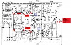
The problem seems to at the Base of Q13 (the PNP driver), which only has about -0.45V when warm, and it should be close to -1.3V.
The base voltages of both drivers change during warm up - they become increasingly uneven.
Please see attached schematic, where I have also noted some voltages.
The rail voltages are all very close to the schematic values.
The question is why? What can be the cause of this?
I have spent quite a few hours trying to find the fault, and have one by one replaced the following transistors (to try something..):
The Q12/Q13 drivers (with a matched pair).
Q4/Q5 and Q6/Q7.
The STV-3H triple diode, and the VR2 bias trimpot.
All the plain signal diodes.
- All the replaced components test good out of circuit, and the DC offset is still the same (but no worse).
I have also tried removing first one output pair, and then the other, but it didn't make any difference.
Seems like it is a simple issue, but it just eludes me, so would greatly appreciate some help 🙂
Starting point:
All electrolytics are new.
All other components have been measured and checked (several times).
I found only one defective diode: D3.
It works and plays music just fine, and THD is normal.
BUT: As the amp warms up, the right channel drifts from DC offset at basically zero, to about 650-700mV (a rather suspicious value..).
The left channel only drifts around 30mV, which seems normal/reasonable.
Initially I suspected the input stage, but it measures well balanced, app. 100mV on all Bases of Q2 and Q3.
The problem seems to at the Base of Q13 (the PNP driver), which only has about -0.45V when warm, and it should be close to -1.3V.
The base voltages of both drivers change during warm up - they become increasingly uneven.
Please see attached schematic, where I have also noted some voltages.
The rail voltages are all very close to the schematic values.
The question is why? What can be the cause of this?
I have spent quite a few hours trying to find the fault, and have one by one replaced the following transistors (to try something..):
The Q12/Q13 drivers (with a matched pair).
Q4/Q5 and Q6/Q7.
The STV-3H triple diode, and the VR2 bias trimpot.
All the plain signal diodes.
- All the replaced components test good out of circuit, and the DC offset is still the same (but no worse).
I have also tried removing first one output pair, and then the other, but it didn't make any difference.
Seems like it is a simple issue, but it just eludes me, so would greatly appreciate some help 🙂
Attachments
Q2 and Q3 are notorious for losing their match after time. What are the collector voltages on Q2 and Q3? I think those would be my first candidates for being bad.
Craig
Craig
Hi Craig, yes I also suspected Q2 and Q3, so much I actually tried replacing them with two well matched pairs of KSC1845 and 992. But it made no difference.
Regarding the Q2 and Q3 collector voltages, it measures about +/-62V - very close all round. Also, the bases on Q4 and Q5 are matching at the same value. It is only after Q6/Q7 I can measure any difference between the negative and positive side.
Edit>> Driver transistor Emitter measurement: Q12 = 1.04V and Q13 = 0.15V. This is fairly warm, with DC offset at 0.55V.
Last edited:
I still can't find the cause of the drift in DC offset..
Since last, I have also tried swapping output transistors from the good channel (left), but that didn't make any difference.
I have just about run out of things to try, but still something on this output board gradually causes a gradual drift in DC offset of app. 650mV.
The problem seems to be on the negative rail side (the "bottom half") of the circuit, and shows itself after Q7 collector, which is also the Base of the Q13 driver. Voltage on Q13 base is definitely too low when the amp is warm.
By now, I have replaced or tried swapping all Transistors on the negative side, except Q11- which measures fine, and shouldn't be able to cause this issue anyway.
All resistors measure good, when cold at least, and the electrolytics are new.
I have tried freezing spray on every component, but nothing gives more that a minor drop in the DC offset.
Something must be wrong somewhere though, but what can it be? 😕
Due to 650-700mV looking suspiciously like a diode drop, I have focused on the transistors and diodes, but could it simply be a resistor that drifts significantly in value as it is "working"? The resistors around the DC balance adjustment are of course critical, and I could try replacing them, although the measure in spec.
----
Another thought: I have been wondering if this amp would benefit from a capacitor in the NFB circuit? It would at least reduce the DC offset issues in general, and should make the amp more stable/safe.
Although Accuphase in the 1978 brochure wrote "... the DC cut capacitor of the NF loop which requires a large capacity is removed and the coloration is removed"
- But these days it seems to be standard good practice with a DC blocking cap, which makes good sense to me.
Attachments
Yes it reacts to VR1.
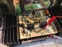
The original trimmer was very touchy though, so I changed it out for a multiturn type (the blue in the photo). Also to rule out a fault with the old trimpot.
I have it adjusted to about zero offset at cold now, but can also adjust it close to zero in warm condition, however, then I will just get offset around -650mV on the next cold start.
Did you check followers Q1 ?
The case of it can be turned around (pinout symmetry), does the offset change then ?
The case of it can be turned around (pinout symmetry), does the offset change then ?
Hi, I have just tried what you suggested: Turning Q1 around 180 degrees, and see if the offset changed: It did not make any difference - offset and polarity is the same as before.
However: I also tried adding a Cfb, a DC blocking cap in the NFB loop, by lifting one end of R16 and placing the cap in series. See pic..
I have done it, so I can easily short out the cap, and see the effect with/without the DC blocking cap.
Result: The cap reduces the DC offset to almost zero!
So that's great! However, it is kind of "cheating", as there must still be a reason for the drifting DC, the capacitor just treats the symptom.
That a DC blocking cap in the NFB loop basically removes the offset, seems to be a clue as to where the offset actually comes from. I just can't figure it out...
Attachments

Last edited:
One thing I thought of is to use some can'ed air to selectively cool things off. You mentioned it is ok cool, but then drifts as it heats up. How long does it take to heat up? You could really go crazy I guess and build a little jig with maybe a 50ohm 2W resistor connected to a 12 power source and locally preheat areas before turning it on. I know I spent way too much time figuring out the beta of the input stage of an amp had degraded and the input bias current increase thru the different input resistances caused a high input offset.
Post 8 - it seems Q1 is fine.
DC blocking cap : result as expected.
Are voltages on D1, D2 the same ?
Did you have offset before "recapping" ?
DC blocking cap : result as expected.
Are voltages on D1, D2 the same ?
Did you have offset before "recapping" ?
D1: +24.8v
D2: -24.9v
The difference of 0.1v stays pretty constant from cold to warm.
Before "recapping" the amp didn't really work, so I don't know. It had many bad solder joints and function was unstable. I have reflowed all solder joints.
D2: -24.9v
The difference of 0.1v stays pretty constant from cold to warm.
Before "recapping" the amp didn't really work, so I don't know. It had many bad solder joints and function was unstable. I have reflowed all solder joints.
So D1, D2 and their caps are fine.
It seems Q2, Q3 are no longer original ?
These, if original in a single case, can be
reversed also in order to check for changes.
It seems Q2, Q3 are no longer original ?
These, if original in a single case, can be
reversed also in order to check for changes.
Yes I have replaced Q2 and Q3 to try and fix the offset issue. They are replaced with matched sets of SC1845 and SA992. It didn't help. The original dual Transistor worked just as well - but no better.
I am thinking about replacing all the DC critical resistors, even though they measure perfectly fine (and most have been checked out of circuit), as I don't know what else could be wrong.
I am thinking about replacing all the DC critical resistors, even though they measure perfectly fine (and most have been checked out of circuit), as I don't know what else could be wrong.
why have you changed d5 (stv-3h.....)?
Not quite random: They are known for failing, so it's basically preventive maintenance on a 40 year old amp.
Since I couldn't pinpoint the fault, I have gradually (one by one) replaced or swapped around transistors (from the other channel) that could be causing the issue. This is also not random, but logical fault finding: When all the likely causes of the issue has been checked, I have to move on to the more unlikely causes - and last resort is just replacing all components (but really hope it wont get to that..).
But this one is not responsible for offset and you verified proper ac operation before.
I can not confirm that these fail, only after catastrophic damage of the power output.
I can not confirm that these fail, only after catastrophic damage of the power output.
can you measure the voltage drop across the emitter res R!8,R19,R20,R21
when cool and warmed up?
when cool and warmed up?
Dear JVHB
I am having also "assymetric trouble", so I searched the forum and found your thread.
Your problem is thermal related, that´s for sure. Sometimes resistors, specially with higher value, "opens" up. There´s a contact between body of the resistor and a metal cap. Due to thermal stress this contact may become unstable. Try to hook up your multimeter on especially carbon types and heat them slightly(turn amplifier off)..Focus on the resistors around input pairs.
Make sure also, that amp is not oscillating - with oscilloscope.
- Home
- Amplifiers
- Solid State
- Accuphase E-303 DC-offset issue