More precisely adjusted , R1 is 1.46k . The amp has a gm of 5.07S to 9.55S from 0A to +/-4A for 0 to +/-34 v output. I will put aside this low impedance version to simmer as I will reconsider back the high impedance one.
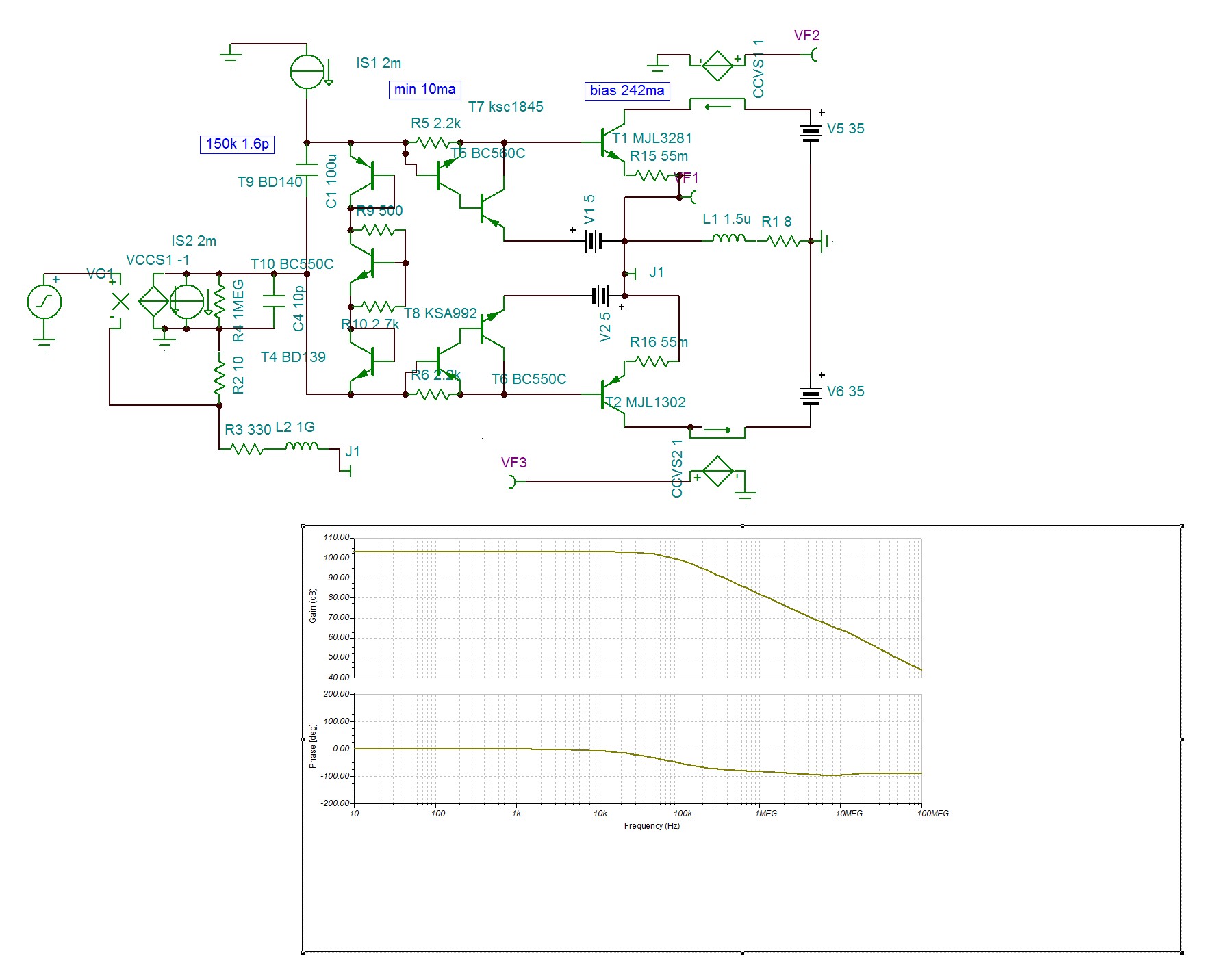
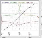
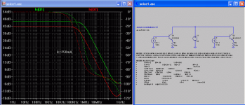
This is the high impedance version with 1M ohm /10pf source that can be VAS. The transfer function of this version can be seen only in closed loop. For that I simulated a CFA error amp of 0.1S . I increased the sense resistors to get the impedance of the amp 176k has 1.6pf. You can see on the open loop transfer function that it doesn't have any pole but that of the VAS . In fact , the pole is dermined by it's 1.6pf which comes in parallel with that of the VAS , hence the 3stage amp becomes 2 stages .
The I/V transfer function is more than cubic function. If with the other version I have the second derivative is decreasing instead of constant to be cubic law , here on the opposite it is increasing . This is generous of its part because the total transfer function depends also , with less importance , upon error amp and VAS. As these generat on phase odd harmonics they will be erased by decreasing the outputs excess .
The I/V transfer function is more than cubic function. If with the other version I have the second derivative is decreasing instead of constant to be cubic law , here on the opposite it is increasing . This is generous of its part because the total transfer function depends also , with less importance , upon error amp and VAS. As these generat on phase odd harmonics they will be erased by decreasing the outputs excess .
Attachments
Transforms the 3 stage to 2, let me laugh. The spice model for MJL3281&Co is fake. Besides the Re not implemented the Ft also is absent. In the model file the parameter Tf & its variables are present but do not work. The model I have is provided by the Onsemi , probably intended to sim gamers as winning transistor . Cordell's model is the same also from Improved SPICE Models for MJL3281A and MJL1302A - Section 1. I will restart with 5200/1943 , at least the models ,although not exact but work.
It seems to be working. Is the error amp actually 1S?This is the high impedance version with 1M ohm /10pf source that can be VAS. The transfer function of this version can be seen only in closed loop. For that I simulated a CFA error amp of 0.1S . I increased the sense resistors to get the impedance of the amp 176k has 1.6pf. You can see on the open loop transfer function that it doesn't have any pole but that of the VAS . In fact , the pole is dermined by it's 1.6pf which comes in parallel with that of the VAS , hence the 3stage amp becomes 2 stages
Cubic laws are only observed in open loop, that is common emitter (ground node to load moved to the usual output node so the supply voltage sources float as Post 11). When you connect as a follower there is negative feedback at work which transforms the cube-laws to something with gain plots more like the tanh(x) when plotted using Vin. So you only see the cubic function (a ramp second derivative) when plotting open loop (or against the internal drive voltage eg base T7 to VF1 node).The I/V transfer function is more than cubic function. If with the other version I have the second derivative is decreasing instead of constant to be cubic law , here on the opposite it is increasing . This is generous of its part because the total transfer function depends also , with less importance , upon error amp and VAS. As these generat on phase odd harmonics they will be erased by decreasing the outputs excess .
For those wondering what on earth cube-laws are useful for😕. There are two useful features:
1) In push-pull and class-A (where both devices are conducting) and in open loop you get fundamental plus third harmonic - no high order harmonics if pure cubic functions. This third harmonic falls in amplitude naturally at lower power levels and is not audible most of the time if the Class-A power region is quite high (at least 10W). Usually some negative feedback is added to the output stage to get a useful damping factor for standard voltage driven speakers and it does not need much negative feedback to make the 3rd harmonic inaudible at high powers. The amount of feedback that is present in most output stages as followers is sufficient to make the 3rd harmonic inaudible at high powers. So 3rd harmonic generations is really a non-problem if done right.
2) In push-pull Class-AB where one devices stops conducting you get negligible high order harmonics at this crossover with pure cubic functions. This is because the gain just before one device turns off continues to rise in the same manner as after one device turns off - so no gain step at crossover! This means you can reduce the idle current to about half of what you would have need for pure class-A (both devices always conducting) and yet not get any audible crossover distortion from Cube-law Class-AB operation (like circuits here with 200mA bias). So you can get Class-A sound quality from Class-AB using this approach. Most still assume that is not an option, but here it is.
Hello Ian.
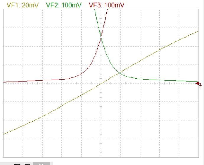
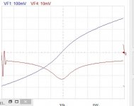
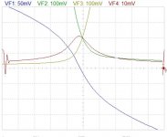
For me cubic function is f=x³ . The first derivative must be a ramp. The red curve is the first derivative of the input grounded amp injecting to its output 10khz triangle wave of 5A peak. you can see , besides the problem, that it is as marguerite instead of being V shape. With the high impedance version ,applying 40db feedback , the marguerite becomes tulip . By the way the distortion at 1khz 34.5vp is 0.0009% mainly odd opposite phase . Next week I show you how it will get decreased by subtraction with that of the preceding stages. For now I am stuck with the American MJLs . The spice models are not time dependent , as if Ft infinity , So I did not advance much today.
Pass a good evening.
Attachments

Hi kokoriantz;
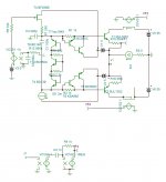
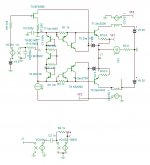
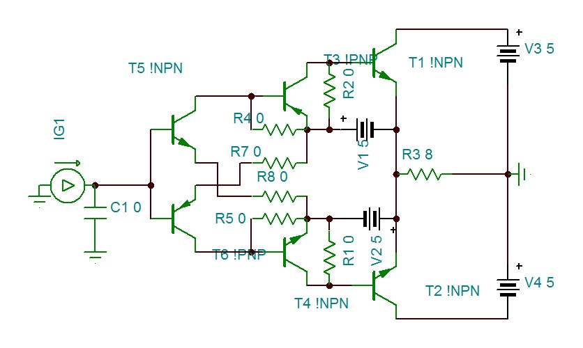
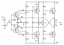
See Post 5 NON-SWITCHING complimentary output stage image repeat below for convenience
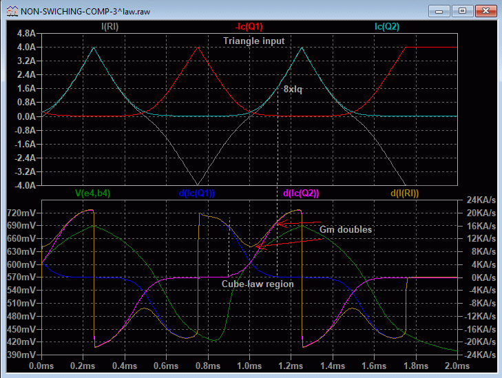
The first derivative d(Ic(q2)) is a parabola within the cube-law region. When two complementary parabolas are added you get an offset parabola, starts at Gmo at idle and doubles to 2Gmo at the end of the cube-law region (where the other side gain goes to zero). At higher currents you have Class-AB where the Gm heads toward linear (mainly due to emitter degeneration in the power transistors). All these are open loop using the common emitter arrangement and when used as a buffer the gain variations get squashed down flatter due to the internal negative feedback inherent in the follower.
When analyzing new topologies like this one, plotting derivatives is indispensable to understand what is going on and to get the best from it. Derivatives also show up ringing and instabilities that you may otherwise miss in current plots from a transient simulation or a frequency plot. Good to see you are plotting the derivative of the output voltage (VF1).
BTW the Cordell model the the MJL1302/3281 do not include Rs values. I also found this to be an issue when no emitter resistors are used as in some of my circuits. (Re may be zero since the datasheets do not provide the information needed to extract Re separate from the base resistance - but some Re is needed for correct gm plots and some finite Re is needed for SOA thermal stability with very low external emitter resistors for electrothermal modeling, maybe in the range of 30m to 50m ohms).
But for most standard amplifiers this shortcoming of Re=0 in the BJT model is not an issue because large emitter resistances are added in the emitters. Also in LTspice the FT is finite in a .trans simulation. Maybe TINA treats the BJT model's FT differently to LTspice?
Keep up the good work🙂.
Hello Ian.
For me cubic function is f=x³ . The first derivative must be a ramp...
See Post 5 NON-SWITCHING complimentary output stage image repeat below for convenience
The first derivative d(Ic(q2)) is a parabola within the cube-law region. When two complementary parabolas are added you get an offset parabola, starts at Gmo at idle and doubles to 2Gmo at the end of the cube-law region (where the other side gain goes to zero). At higher currents you have Class-AB where the Gm heads toward linear (mainly due to emitter degeneration in the power transistors). All these are open loop using the common emitter arrangement and when used as a buffer the gain variations get squashed down flatter due to the internal negative feedback inherent in the follower.
When analyzing new topologies like this one, plotting derivatives is indispensable to understand what is going on and to get the best from it. Derivatives also show up ringing and instabilities that you may otherwise miss in current plots from a transient simulation or a frequency plot. Good to see you are plotting the derivative of the output voltage (VF1).
BTW the Cordell model the the MJL1302/3281 do not include Rs values. I also found this to be an issue when no emitter resistors are used as in some of my circuits. (Re may be zero since the datasheets do not provide the information needed to extract Re separate from the base resistance - but some Re is needed for correct gm plots and some finite Re is needed for SOA thermal stability with very low external emitter resistors for electrothermal modeling, maybe in the range of 30m to 50m ohms).
But for most standard amplifiers this shortcoming of Re=0 in the BJT model is not an issue because large emitter resistances are added in the emitters. Also in LTspice the FT is finite in a .trans simulation. Maybe TINA treats the BJT model's FT differently to LTspice?
Keep up the good work🙂.
Last edited:
I agree with you 100% , but you are forgetting the driver's x² function multiplies with the output's, The sense resistors parallel to the driver B,E gives in total x²+Rx . If the total funtions were parabolas , than in biased classA zone it would result a linear output current , that has a derivative zero. You can see my latest adjustments that in class A zone the derivative which is the inverse function of the output impedance , hence to be called the conductance of the output , is not zero except very tiny zone , but linearly varying conductance region of about 0.5A , The V shape zone. Ok it is not much , but with my 97db,106db loudspeakers ,2W is sufficient to quench my curiosity to hear, what kind of sound does such theory amp can give.
Attachments

Last edited:
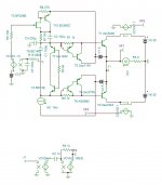
Hi kokoriantz,Can you try this please on LT?
Here. So there is a difference with your TINA MJL3281 model.
LTspice does have a finite "FT".for the Cordell MJL3281.
Strictly speaking this is the Fbeta since the base is current driven.
Attachments
So , What the people want is a class AB amp that has similar linear character of class A , than I will design one . If it is required that the output conductance is to remain linear as class A , it is out of question to let Ic/Vcb square law activate. Even if you get linearized crossover region and linearized by emitter degenerated high current region , you will always get in between square law . The only way to have linear transfer function is to use Ic/Ib Beta mode. If once upon time transistors at 2N3055 era had chaotic Hfe , with Fbeta 20khz only , nowadays they have ultra linear with Fbeta of 1Mhz but designers are still using topologies intended for once upon a time transistors. This going to change .
Attachments
Last edited:
Thank you Ian. Very sad for me.
Hi kokoriantz,
That may explain how come my LTspice version was oscillating when yours wouldn't oscillate.
Yes, it is disappointing when models are found to be inadequate - especially when trying to understand how a new circuit works. It's a bit like trying to debug a faulty amplifier with a faulty multi-meter, and you don't know it is faulty until way down the track.
So don't give up on your non switching topology too soon. I have not seen it done that way before so you could have it named whatever you choose. It would be good if a version can be made and listened to, so we can be sure whether it has the good audio qualities it appears to present in simulations.
Last edited:
Than you Jan for your support. I will modify the working C5200&Co files with the parameters of MJLs . I did remark from your sim that the model is far to be exact. The beta is about 180 were the spec. says max 150. Worse, the Ft at 250ma the spec. says 30Mhz. Than Fbeta =Ft÷beta should give 166khz , your sim shows 1Mhz. This is unusable. I never abandon , but let it simmer until I get new ideas. This current amp version is also non-switching but not cubic or square function . As we on another thread dealt with current biased output , I said why we don't join our expertise in this domain to get a linear transfer current booster .
So , What the people want is a class AB amp that has similar linear character of class A , than I will design one . If it is required that the output conductance is to remain linear as class A , it is out of question to let Ic/Vcb square law activate. Even if you get linearized crossover region and linearized by emitter degenerated high current region , you will always get in between square law . The only way to have linear transfer function is to use Ic/Ib Beta mode. If once upon time transistors at 2N3055 era had chaotic Hfe , with Fbeta 20khz only , nowadays they have ultra linear with Fbeta of 1Mhz but designers are still using topologies intended for once upon a time transistors. This going to change .
Hi kokoriantz,
The circuit shown (with T2 PNP) has no resistance values. Is it a serious topology? Is it Class-A or Class-AB?
Re: Quest for amplifiers with Class-A character (but economical as Class-AB).
This has been the aim of amplifier designers for the past 60 years since transistors were used. The THD has fallen progressively and commercial amps have been available with ppm THD, eg Halcro 1994 circuit here US5892398A - Amplifier having ultra-low distortion
- Google Patents and review here Halcro dm38 power amplifier | Stereophile.com
And what did it sound like? Reviewers were not satisfied with what they heard. Why? Because they liked tube amplifiers more than distortionless amplifiers!
This is an enigma that I have thought long and hard about since I read the Halcro review 2 decades ago. I slowly came to the realization that amplifiers need to clip softly - not hard clip like 99.9% of solid-state amps do.
Bob Cordell helped me along the way. He did an Audio Engineering seminar where he showed even 250W amplifiers do clip quite often even with not too loud music!
So when a reviewer takes care not to clip solid-state amplifiers they don't give as good a sound as a tube amplifier that soft clips because the tube amp gives more 'punch' per watt rating. The single digit ppm THD readings of the solid-state amp doesn't count much in this type of listening test.
And if all that is true then what we need is solid-state amps with soft clipping. And if all that is true we don't really need such low THD readings.
The amplifier I arrived at based on this thinking was published in Linear Audio Volume 8 and updated Volume 13. A free supplement gives an overview of the developments and references here Cube-Amp_LACAv8-Supplement-2+_08Apr2017.pdf - Google Drive
Re: Using "designers are still using topologies intended for once upon a time transistors."
One reason Douglas Self gave for this in his book(s) is the standard topology (Bob Cordell calls the Thompson topology) is it is easy to make it work. Nearly every aspect of it has been under the microscope and there are not may surprises when making one anymore - they just work.
As for topologies using common emitter or common source output stages there's nothing in Bob Cordell's book or Douglas Self's book on these and there are are few on diyAudio and other forums who are experienced in both standard and alternative output stage topologies.
Here on diyAudio, alternative topologies like in the Pass section, some of which are common source like the F5 and F6 etc, are kept separate from the solid-state amps section. Similarly, alternatives like tube amps are separated out from the mainstream amplifier section. This is helpful because of the volume of postings but it locks designers into narrow thinking, and it's just one of the many reasons why its very hard to get any traction on alternative solid state topologies.
I encounter the question: "how come my designs have never made it commercially?" To that I say, "everything has been off-shored, so how can I?!!". The best I can do is help other DIYer's make alternative amps. So I'm here to help.
Cheers,
Ian
Last edited:
Being son of self learned TV repair , I started at the age of six repairing radios. At 11 I was already earning by own bread. In early 70's, an Italian pro boxer , invited by the military for training , brought me two second hand Grundig radios to repair. One was a small for bedroom and a giant furniture stereo type . Once repaired I was astonished the extraordinary sound of the small radio EL84 SE output, but the large furniture with PP EL84 , yes far powerful ,nothing but ordinary . Since, I entered in the world of Audiophiles . On summer times I went to work for free with a great hifi guru of middle east servicing Pioneer brand serving the richest and famous of the country. In exchange of my free repairs he thought me how to listen the sound , what makes good , what makes bad . Simple example , Listen the music from that time Happy Together of the Turtles on your beloved amplifier. You can hear how the refrain by the chorus is so difficult to reproduce cleanly.
I my topology presented yesterday , the middle transistors go cut off . To make them work in class A , instead of pumping current in its output , it must pull the high biasing excess current from the opposite output. Such topology already exist

I will start from this amp and transform it to floating bootstrapped supplied drivers with unity gain.
By looking the price of MJLs on Aliexpress , I saw that the newer NJW3281/1302 is far more available and costs half of the price . The specs are identical to the MJL's with better Ic/Vbe curves. ONsemi providing 3 types of spice models . I used the spice3 on Tina , it works well except the Hfe is 300 instead of 100 typical. I had to divide the BF numbers 119/100 by 4, 40/25 to get them at 100. Now, the FHfe measures correctly 300khz/250khz.
MJL3281/1302 ? FORGeet it.
Attachments
Last edited:
Hi KK,
I applaud your attempts to reach non-switching, and know that it's very difficult.
LTSpice has a FFT, so you can run any signal through it for harmonic profile. This is very helpful, as we know the best sound will be a monotonic decrease of the (inevitable) harmonics, with H5 and beyond lower than -100dB.
I have found that only Class A can do it well, and my latest is the Alpha Nirvana. But it's a horrific energy consumption, 100W consumption for 39W audio.
I did find with a quasi amp that if you use large differences in transconductance with the output stage, you can keep at least one of them alight even at full power. I used a lateral fet and a bipolar, and with quiescent of 150mA the minimum current through the lateral at full power was 42mA. The profile was excellent.
These are empirical results, I'm not sure if that helps you KK, you are exploring the theoretical and schematic issues at the moment.
Ian,
I'm really enjoying your input, thank you!
Hugh
Last edited:
- Home
- Amplifiers
- Solid State
- Non-switching complimentary output stage