Hello!
I have a Technics SA-424 which I lake very much because it has a build-in AM/FM receiver with analog and digital metering.
The issue that I experiencing is that I lost the ability to select from the preset channels, to tune and also I've lost the LCD output.
Long time ago I’ve started to check the machine I made some replacements.
As you can see at the schematics on E section (main amplifier circuit) there is a spot which is the power supply for some parts of the system in between of is the supply of the C (FM/AM preset tuning circuit).
For the pin out 17 to 23 I couldn’t take the measurements that I should have.
The replacements that I did are Q703,704 with the original 2SC1815 (just for renewal reasons),
Q703 – 2SD880 with a BD241C (which I believe that it is not the correct I will explain later),
all the electrolytic capacitors C708,709,711,712,713,716 and the diode D712 -svdsr1k2 with a 1N4007.
Then I had assembled again the parts and I fired up the amp. I saw for a few seconds light on my monitoring but right then I lost it.
So after farther reading I realized that when you try to fix a Japanese amp circuit is not a so easy.
I have some doubts regarding the Q703. The specs says that I should have a rank of Y or O and the BD is a C. Watts more is that I am not sure if the electrical characteristics are similar.
The same situation for the 1N4007 which I believe it should be the 1N4007 but I am not sure if it maters at all.
Can somebody guide me through this?
And one more thing… When I measure on pin 36 I have 36V AC. When I measure on D711 at anode I have 2,5V dc. Is that correct?
Attached the schematics
For more detail the service manual is at Technics SA-424 - Manual - FM/AM Stereo Receiver - HiFi Engine
Attachments
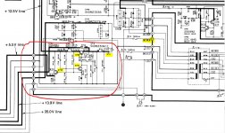
Diode D712 should be replaced by a "6v zener diode", you can not use 1N4007.
The voltage after D711(can use 1N4007) on C711 should be around 44V, you measured a 2.5V means something wrong on the caps or regulator supply circuits, please check "C711/C712 for any short, R711 for open"
For Q703 transistor, you can just use "BD214C" to replace and no need to consider the original transistor hfe rank of Y or O. Please check the voltages "Base 15v, collector 31v, emitter 14.4v"
The Q703 output 12.5v with high current 158mA to tuner circuit, please "measure the 12.5v to ground resistance" if there is a short in the tuner circuit.
If transistors Q704/Q705 and D712(6V zener) all ok, you should have a correct "voltage outputs according to the schematic".
Any different voltage value in the transistor pins, you should check the transistor, caps and resistors around it.
For no display(vacuum fluorescent display), please test the "AC 6V and check R710"
Attachments
Last edited:
Sorry it's a typo.
He used a BD241C to replace Q703
https://www.onsemi.com/pub/Collateral/BD241C-D.PDF
He used a BD241C to replace Q703
https://www.onsemi.com/pub/Collateral/BD241C-D.PDF
I think that I made a typo for the D712… I am talking about D711 and you gave me an answer.
Regarding the measurements can tell you briefly that I didn’t read correct values, if my mind help me I remember that for Q703 I had lower values than the schematic depicts.
But I will check again the following days and I’ll come back with an update.
Regarding the measurements can tell you briefly that I didn’t read correct values, if my mind help me I remember that for Q703 I had lower values than the schematic depicts.
But I will check again the following days and I’ll come back with an update.
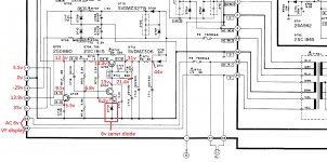
ok... after many hours of taking measurements  i have this...
first of all i measure all the components around the mentioned area out of the circuit and i found them ok! (strange...)
Then i was trying to focus to why i do have this voltage drop on D711.
The result is that if i remove R719 and Q703 the voltage on D711 is around 41Vdc.( than 3.5, looks better )
When i put Q703 again the problem comes up.
Then with Q703 in circuit but with R712 and R719 out of it i have again the correct value on D711....
And last but no least when i put back R719 but not R712 i have again the problem...
Some more observations....
The R712 and R718 are above R711 and the area is a little bit burned.
When the circuit has all the parts on R719 is too hot!!!!
who is the culprit?
technics snap 1 — Postimage.org
technics snap 2 — Postimage.org
i have this...first of all i measure all the components around the mentioned area out of the circuit and i found them ok! (strange...)
Then i was trying to focus to why i do have this voltage drop on D711.
The result is that if i remove R719 and Q703 the voltage on D711 is around 41Vdc.( than 3.5, looks better )
When i put Q703 again the problem comes up.
Then with Q703 in circuit but with R712 and R719 out of it i have again the correct value on D711....
And last but no least when i put back R719 but not R712 i have again the problem...
Some more observations....
The R712 and R718 are above R711 and the area is a little bit burned.
When the circuit has all the parts on R719 is too hot!!!!
who is the culprit?
technics snap 1 — Postimage.org
technics snap 2 — Postimage.org
Last edited:
Risistors R711 3W, R719 2W they are in high watts so that they will dissipate heat and burned the PCB after long time, so that after a period of time, these burned area resistors and caps should be checked if a new replacement is needed.
you try disconnect the load form the supply by disconnect the output or cut the PCB and just test the supply circuit voltages.
you try disconnect the load form the supply by disconnect the output or cut the PCB and just test the supply circuit voltages.
Attachments
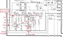
Yes of course.Risistors R711 3W, R719 2W they are in high watts so that they will dissipate heat and burned the PCB after long time, so that after a period of time, these burned area resistors and caps should be checked if a new replacement is needed.
Is my fault that i haven't told you that the measuring that i did was without the tuning board connected. J108 connector is open. But i will do the same with J109. Thus i can't understand your last advice...
 Can you please clarify your thoughts.
i did was without the tuning board connected. J108 connector is open. But i will do the same with J109.
You mean you test this power supply board voltages with no load(tuning board) connected. If like this, I will think again.
You mean you test this power supply board voltages with no load(tuning board) connected. If like this, I will think again.
Yes.....
Do you use an insulator film to mount Q703, maybe the back of the transistor shorted the heatsink to the ground
Never.... this is the interesting... i am trying to identify if i have a short somewhere...
https://i.postimg.cc/HLLggR4Y/power.jpg
Please connect a Bulb Tester circuit to test your amp
I don't have...


I don't have...
Sorry it is "Dim Bulb Tester"
It is very simple and low cost, just connect a 60W bulb between one the AC line input and then to the amp.
It is very simple and low cost, just connect a 60W bulb between one the AC line input and then to the amp.
i am on my way to built one....
- Status
- This old topic is closed. If you want to reopen this topic, contact a moderator using the "Report Post" button.
- Home
- Amplifiers
- Solid State
- Technics SA-424 FM/AM preset tuning circuit LCD lost