Handel,
I have made an LTSpice model for easier finding of problems.
Since the input section seems to work properly, I have simulated this with an OpAmp, giving exactly the same steering signal through current sources B1 and B2 as your transistors Q25 and Q26.
In the two circuit diagrams you will find the respective voltages at critical spots.
All names of resistors and transistors correspond with your schematic diagram.
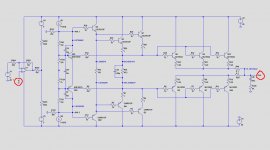
1) The first image below shows the complete output section, but with 3 output transistors instead of 6, which won't make much difference in this case.
Since most transistors in your amp are not all available as LTSpice models, I have used versions that come close.
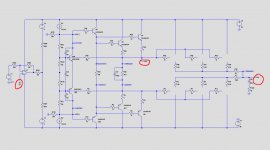
2) In the second image I have omitted the output transistors and connected the output (in your schematic 'f') to the junction of R34 and R26 as in step 3) that you tried before.
Hope that this helps you a bit.
Hans
P.S. This replaces an earlier versiomn that was wrong.
I have made an LTSpice model for easier finding of problems.
Since the input section seems to work properly, I have simulated this with an OpAmp, giving exactly the same steering signal through current sources B1 and B2 as your transistors Q25 and Q26.
In the two circuit diagrams you will find the respective voltages at critical spots.
All names of resistors and transistors correspond with your schematic diagram.
1) The first image below shows the complete output section, but with 3 output transistors instead of 6, which won't make much difference in this case.
Since most transistors in your amp are not all available as LTSpice models, I have used versions that come close.
2) In the second image I have omitted the output transistors and connected the output (in your schematic 'f') to the junction of R34 and R26 as in step 3) that you tried before.
Hope that this helps you a bit.
Hans
P.S. This replaces an earlier versiomn that was wrong.
Attachments

It almost looks as if all voltages in the sims above are negative because the minus sign coincides with the line before.
But just assume that all upper figures are positive and the lower ones negative.
Hans
But just assume that all upper figures are positive and the lower ones negative.
Hans
Wow, you are amazing Hans!
I made the light bulb measurement. I attached 40W bulb between the unregulated voltages and the bulb was shining like a star. Voltages were very close to + and -86V. Ripples were 500mV in positive side and 330mV in negative side. smaller was more like sine wave. Bigger like phase modulated signal 🙂
How much ripple is tolerated in these unregulated voltages?
Wow, you are amazing Hans!
I made the light bulb measurement. I attached 40W bulb between the unregulated voltages and the bulb was shining like a star. Voltages were very close to + and -86V. Ripples were 500mV in positive side and 330mV in negative side. smaller was more like sine wave. Bigger like phase modulated signal 🙂
How much ripple is tolerated in these unregulated voltages?
With the 40Watt bulb, you are drawing ca 0.25A.
I=C*du/dt, so 500mV ripple means C = 0.25A*10msec/500mV = 6000 uF.
On the foto's I saw much bigger elco's so I think they are no longer top quality, but for finding errors in your amp, it's good enough for the moment.
So you measured the voltage over R45, which only gave you 1.2 Volt, much too low because it should be ca. 2.4Volt.
But this 1.2Volt explains why you measured no voltage on R50 and only 2.8Volt instead of 3.6 Volt between WH.1 and WH.5.
So could you do the following test with 'f' still connected to WH.1.
Now connect your multimeter in the current setting between WH.1 and WH.5.
You should read 15.8mA.
Please let me now what you get.
Hans
I measured between WH.1 and WH.2 with 'f' to WH.1. Current was 18.2mA. It is slowly going down. I waited about a minute and it was round 17mA.
I measured between WH.1 and WH.2 with 'f' to WH.1. Current was 18.2mA. It is slowly going down. I waited about a minute and it was round 17mA.
That’s o.k., after warming up it will go to 15.8mA.
But this means that potmeter R124 now should be adjusted.
So with ‘f’ still connected to WH.1 connect your multimeter over R50 and turn the pot until you have ca. 1 Volt over R50.
After that please tell me the voltage on WH.5
Hans
The only way to the 2.8V that you measured between WH.1 and WH.5 is to make R124 500 Ohm.
That's exactly the max value of this pot, so I think the the wiper is no longer contacting the track, because of oxidation.
So before starting your test, it's a good idea to turn the pot a number of times up and down to restore the contact between wiper and track.
Succes.
Hans
That's exactly the max value of this pot, so I think the the wiper is no longer contacting the track, because of oxidation.
So before starting your test, it's a good idea to turn the pot a number of times up and down to restore the contact between wiper and track.
Succes.
Hans
I turned the pot number of times before the measurement and I could not get the voltage higher than 0V over R50. The maximum value of the pot is 443 Ohm which is now set. Voltage in WH.5 is now -2.4V.
I turned the pot number of times before the measurement and I could not get the voltage higher than 0V over R50. The maximum value of the pot is 443 Ohm which is now set. Voltage in WH.5 is now -2.4V.
O.K. There is your problem, there's no current flowing through R50.
1) See if the combination of R50/C55 and C56 are forming a short circuit. That will be easy to measure. It could be that C55 is the cause.
But even when this is the case , you will also have to measure:
2) R9/R34, R26/R27, R1/R4, R36/R13, R25/R28, R2/R3 and last but not least Q29/Q30, Q41/Q42.
Several of these components must be broken.
Hans
Yes, R50 is shorted. I took also C55 and C56 off and they measure right. Strange resistor, it measures 40.2 ohm but still shorted. What I do not undrstand is that also left channel is shorted here. It have been working but maybe multiple turn on and off has broken it.
There must be much more wrong as just R50, because even when it's shorted, there is still no reason why the output was +3 Volt while WH.5 was -80Volt.
So please go on testing the resistors and the 4 transistors.
Hans
So please go on testing the resistors and the 4 transistors.
Hans
I'm very interested in this thread, as I've got a No. 27 that has similarities to the 23, and the coaching by Hans has been instructive to me. Handel - I hope you get this figured out, and my compliments to Hans for his efforts!
Stay healthy.
Stay healthy.
Btw. Hans, There is difference between schematic and PCB. Transistors Q40, 29 and 30 and same in negative side are NOT connected to the VCC unreg. Only bases and emitters are connected. Collectors are left open, cut. ???? I think it can be seen from the photos.
Also when measuring Q40 and Q52 with diode test both directions are passing but they are not shorted.
Also when measuring Q40 and Q52 with diode test both directions are passing but they are not shorted.
Hi Handel,
What a surprise, but I can guarantee you that these transistors should be connected to resp the +Vcc Unreg and the -Vcc Unreg, just as the 12 TO3 power transistors.
How exactly did you remove these 12 TO3 power transistors from the circuit, by unsoldering and taking then out, or by unplugging some wires.
If it's done by unplugging wires, you could also have removed the supply from the 6 pre-driver transistors as well.
But let's take one step back.
You have the luxury of having a second amp that can be used as your reference.
To be sure that this second amp is working 100%, let's do a sanity check.
Only two simple steps to be taken:
1) measure the output voltage, this should be below 25mV
2) measure the idle current in the output transistors. This should be 275 mA.
So when measuring the voltage over R20 or R44, you should see 27.5 mV or 55mV when you measure over both resistors.
I'm a bit alarmed that you measured a short circuit over R50 in the second amp, that's why this sanity check should be taken first.
From there on it will be of great help to compare the two amps, such as checking the unreg power supply on the 6 pre-driver transistors.
Please keep me informed.
Succes,
Hans

I measured the voltage in the output and that is 17.5mV. Idle current is only 50mA. Voltage over R20 and R44 is 34mV.
I have unsoldered 12 output transistors and taken them out.
Sorry I messed with the R50. That measures right and so does the two caps around it. I took those off and measured. Now they are back again. I did not know that the continuity measurement does not work with 50 Ohm and below. And thanks again for the simulations.
- Home
- Amplifiers
- Solid State
- Mark Levinson No23 repair help