Hi Andy,
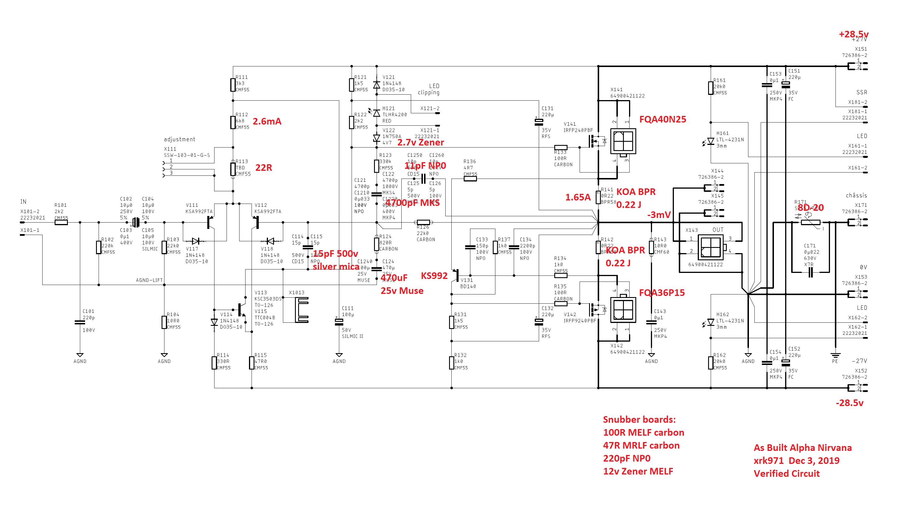
Those are typos, they are supposed to refer to the 5 locations of 4 pin jacks. Each location needs a PCB mounted socket, a wire mounted plug, and the crimp pins for the plug. Hence 3 different parts. 5 locations are for MOSFETs on the main amp board, speaker out, and mosfet snubber boards. The snubber boards are optional as you can solder wires directly to the snubber. The X numbering fo these connectors is actually given in the schematic.
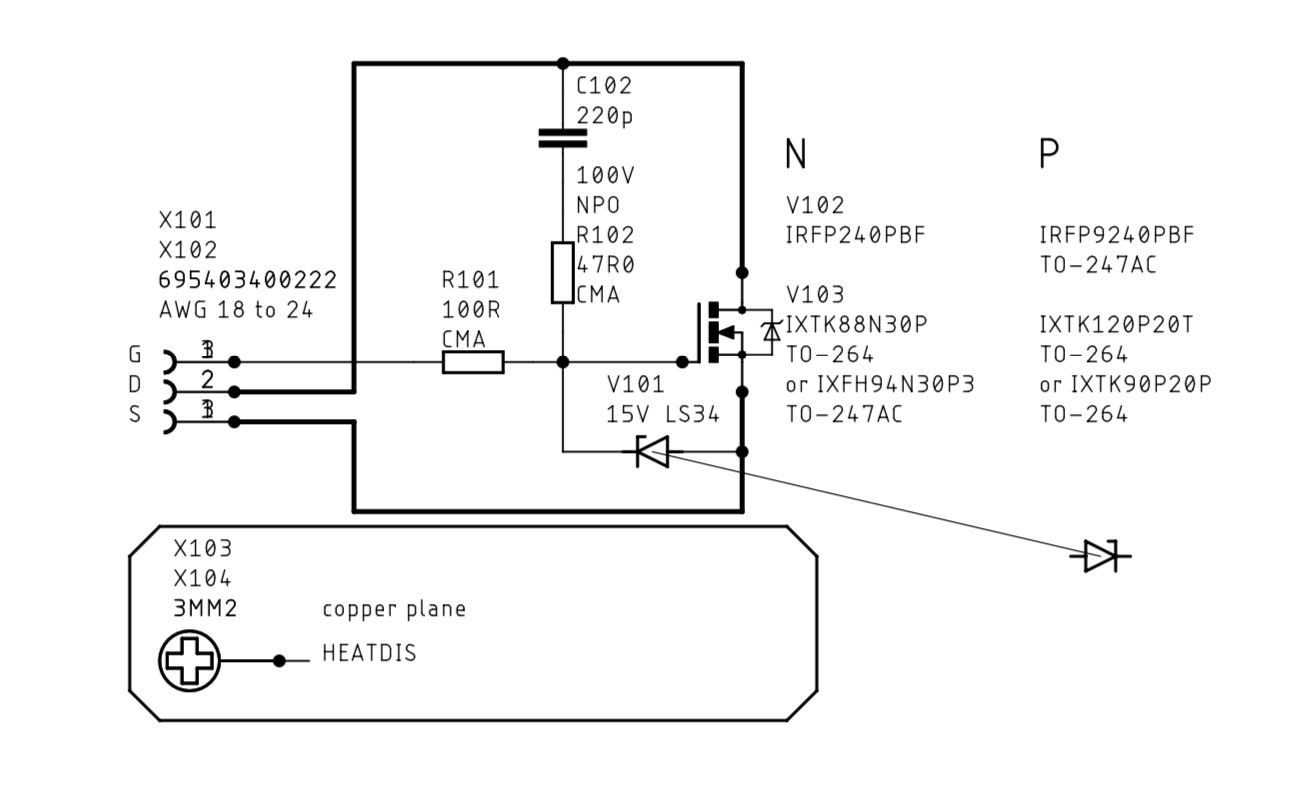
And for the snubbers:
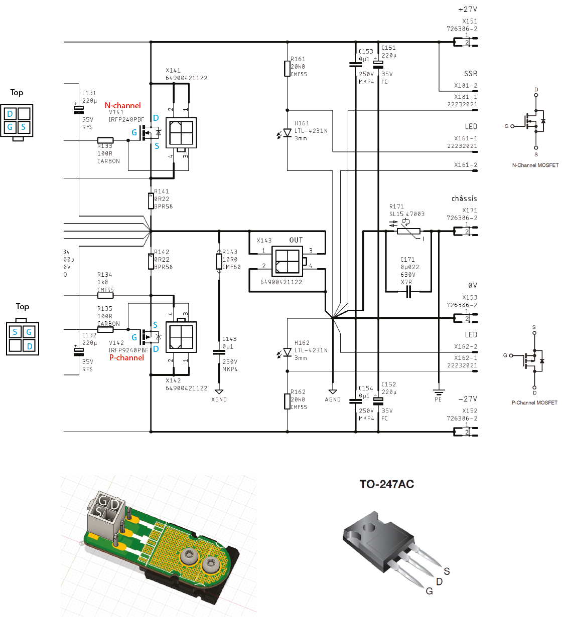
And for the interconnect diagram for the pin locations:
You can see that the naming appears to be inconsistent. But luckily, we know where all the 4 pin connectors go!
Those are typos, they are supposed to refer to the 5 locations of 4 pin jacks. Each location needs a PCB mounted socket, a wire mounted plug, and the crimp pins for the plug. Hence 3 different parts. 5 locations are for MOSFETs on the main amp board, speaker out, and mosfet snubber boards. The snubber boards are optional as you can solder wires directly to the snubber. The X numbering fo these connectors is actually given in the schematic.
And for the snubbers:
And for the interconnect diagram for the pin locations:
You can see that the naming appears to be inconsistent. But luckily, we know where all the 4 pin connectors go!
Okay, the ANs are still running in my lab, so I'm going to give you a further review here... I did a bit some pages back, if you haven't read it check that.
Extended review:
I have monos and the advice is build the MoFo. Seriously, I don't know if Pappa has heard this one, but IMO this is in the Pass phylum. ~ I knew the word, but had to give it a quick Wiki look to make sure I had it right. 😛 I can't give a better compliment then that, unless we are talking tubes, but I digress.
JT
Last edited:
Thank you, JT! Those are indeed kind words for the Alpha Nirvana. To be clear, when you say MoFo above, its colorful language and not the MoFo (Mosfet Follower) amp?
I am listening to my Alpha Nirvana today on some new speakers made with the Visaton B80. A great sounding combo.
Cheers,
X
I am listening to my Alpha Nirvana today on some new speakers made with the Visaton B80. A great sounding combo.
Cheers,
X
Last edited:
You guys did as great job Hugh, if you need some unbiased ears when you bring your tweaked version to the market, I'd be happy to give it a full work-up. I do have all the gear for analyzing, but, what I found is I like what I like and all the pretty numbers/graphs don't mean much to me. I use them more to look at what I like to hear and then, I can run those tests on other equipment and use that as a, "tell" it might be something I like.
I built these to go in my dedicated room, but I spend much more time in the lab, so I'm finding it real hard to move them. When I do get them in there, I will run some tests and post the data. I'm not sure what good that is because no two rooms or chains are likely to be the same, and even if they were, your ears and brain aren't mine.
"Aussie Aussie Aussie, Oi Oi Oi"
🙂
JT
Last edited:
Hey JT,
Sounds like you’re really enjoying your new Bad A** Alpha Nirvana Mono’s!! 😀
I’m highly anticipating the Rebirth of mine also.
Happy Listening!!

Sounds like you’re really enjoying your new Bad A** Alpha Nirvana Mono’s!! 😀
I’m highly anticipating the Rebirth of mine also.
Happy Listening!!
Hi Andy,
Those are typos, they are supposed to refer to the 5 locations of 4 pin jacks. Each location needs a PCB mounted socket, a wire mounted plug, and the crimp pins for the plug. Hence 3 different parts. 5 locations are for MOSFETs on the main amp board, speaker out, and mosfet snubber boards.
You can see that the naming appears to be inconsistent. But luckily, we know where all the 4 pin connectors go!
Thanks, X.
Another Qu - sorry - but this should be my final one. 😱
I'm about to solder in C124. I am using a Black Gate electro here - but I notice there is no '+' mark on the "Printed Board Assembly - Top Side " diagram.
Am I right in thinking the -ve side of the electrolytic should connect to R104?
Thanks,
Andy
I have a question about the reverse sides of the Snubber boards.
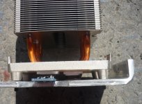
I am going to clamp a P and N Snubber board between a Dell CPU cooler and a 5mm aluminium bracket which, when bolted to the bottom plate of the case, will hold the CPU cooler stack horizontal.
See first attached pic.
So the metal side of each MOSFET will have a ceramic insulating pad between it and the copper pad on the CPU cooler.
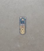
The second attached pic shows the reverse side of a Snubber board.
My question is - given all the vias and the bolt hole lands ... is an insulator also needed on this side (ie. between this reverse side of the Snubber board and the aluminium bracket it is clamped to)?
I'm thinking 'Yes'.
Andy
I am going to clamp a P and N Snubber board between a Dell CPU cooler and a 5mm aluminium bracket which, when bolted to the bottom plate of the case, will hold the CPU cooler stack horizontal.
See first attached pic.
So the metal side of each MOSFET will have a ceramic insulating pad between it and the copper pad on the CPU cooler.
The second attached pic shows the reverse side of a Snubber board.
My question is - given all the vias and the bolt hole lands ... is an insulator also needed on this side (ie. between this reverse side of the Snubber board and the aluminium bracket it is clamped to)?
I'm thinking 'Yes'.
Andy
Attachments

Those vias are purely there for thermal conduction between the top and bottom layer which is isolated from the pins. If you clamp the aluminum bar to the snubber board, those vias will be referenced to the clamp bar, the bolt, and the heatsink - which should all be connected to protective ground. This will reduce noise and prevent oscillation from the capacitor formed between the metal pad of the mosfet and the heatsink surface. So no, you do not need an insulator on the top of the snubber.
Those vias are purely there for thermal conduction between the top and bottom layer which is isolated from the pins. If you clamp the aluminum bar to the snubber board, those vias will be referenced to the clamp bar, the bolt, and the heatsink - which should all be connected to protective ground.
This will reduce noise and prevent oscillation from the capacitor formed between the metal pad of the mosfet and the heatsink surface.
So no, you do not need an insulator on the top of the snubber.
Excellent - thanks, X! 🙂
Andy
PS: But, yes, I will drill a hole in the bracket to earth it to the chassis (protective ground). Just in case the bolts holding the bracket don't do a good enough job of grounding it.
Haha - yes, Hugh ... no questions today. 😀 I was p*ssed off with progress - so I decided to take a break from AN building. 🙂
I found I had a problem with the 5mm aluminium brackets that I had had made up for the CPU coolers. So I could not proceed with clamping the Snubber-boards-with-MOSFETs to the CPU coolers.
The MOSFETs + ceramic insulator pads need to be clamped between the CPU coolers and the aluminium brackets. This means the metal back of each MOSFET (plus its ceramic insulator!) needs to be on the CPU cooler's copper pad - but the rest of each Snubber PCB needs to be in free air (to avoid shorts from the back of the Snubber board to the aluminium bracket).
So I need to have truncated triangles cut into each side of each aluminium bracket.
EDIT - sorry, my attempted diagram has not come out. 🙁
I burnt out my Dremel trying to cut one of these triangles into one of the 5mm brackets. 😱
So I decided to take the brackets to my metal man (who made them up in the first place) to cut these triangles - and I pick them up tomorrow morning. 🙂
But I'm not expecting any more questions! 🙂
Regards,
Andy
Last edited:
The MOSFETs + ceramic insulator pads need to be clamped between the CPU coolers and the aluminium brackets. This means the metal back of each MOSFET (plus its ceramic insulator!) needs to be on the CPU cooler's copper pad - but the rest of each Snubber PCB needs to be in free air (to avoid shorts from the back of the Snubber board to the aluminium bracket)
No, I think you misunderstood what I said in previous post: the back of snubber board where the numerous via pads are can touch the clamp bar or ground. It’s electrically isolated from any of the pins on the snubber board. It’s there simply as a thermal conductivity enhancer and MEANT to be contacted by the clamp bar and GND.
No, I think you misunderstood what I said in previous post: the back of snubber board where the numerous via pads are can touch the clamp bar or ground. It’s electrically isolated from any of the pins on the snubber board. It’s there simply as a thermal conductivity enhancer and MEANT to be contacted by the clamp bar and GND.
Thanks, X.
Yes, the way I have it organised, the back of each Snubber underneath the MOSFET will be in contact with the aluminium bracket. However, the rest of the Snuber board - like, where the MOSFET pins are soldered - will be in free space.
Andy
Hi AndyR,
I’m really confused. There is only one way to mount the MOSFETs to the snubber - with the plastic back contacting the snubber board with legs bent up and all the SMT resistors and snubber cap between the legs and the snubber board as I have shown in my photo.
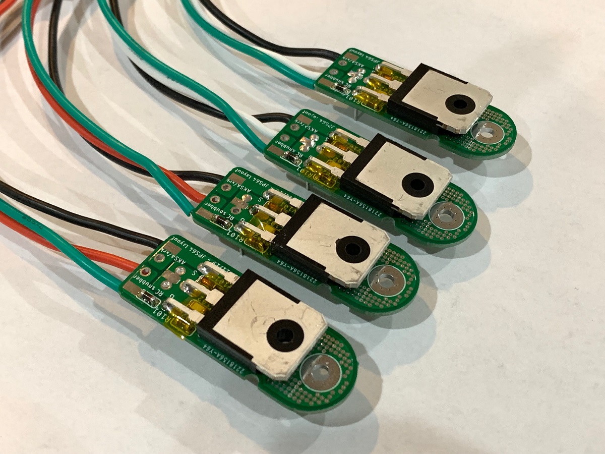
If you mount the MOSFET on the other side of the snubber board, it’s metal thermal pad would be in contact with the snubber and not the heatsink copper pad. If you flip it so that the metal pad is up then pin for G and S are reversed.
Please show a photo of what you mean.
Here is a stack sequence in words. It must follow this:
From top free space Clamp Bolt —> Clamp Bar —> Snubber Board —> MOSFET plastic body —> MOSFET metal thermal pad —> thermal paste —> ceramic insulator —> thermal paste —> copper heatsink surface.
The snubber board will have the SMT parts on the side facing the copper heatsink of the CPU cooler.
I’m really confused. There is only one way to mount the MOSFETs to the snubber - with the plastic back contacting the snubber board with legs bent up and all the SMT resistors and snubber cap between the legs and the snubber board as I have shown in my photo.
If you mount the MOSFET on the other side of the snubber board, it’s metal thermal pad would be in contact with the snubber and not the heatsink copper pad. If you flip it so that the metal pad is up then pin for G and S are reversed.
Please show a photo of what you mean.
Here is a stack sequence in words. It must follow this:
From top free space Clamp Bolt —> Clamp Bar —> Snubber Board —> MOSFET plastic body —> MOSFET metal thermal pad —> thermal paste —> ceramic insulator —> thermal paste —> copper heatsink surface.
The snubber board will have the SMT parts on the side facing the copper heatsink of the CPU cooler.
Last edited:
Hi AndyR,
I’m really confused. There is only one way to mount the MOSFETs to the snubber - with the plastic back contacting the snubber board with legs bent up and all the SMT resistors and snubber cap between the legs and the snubber board as I have shown in my photo.
If you mount the MOSFET on the other side of the snubber board, it’s metal thermal pad would be in contact with the snubber and not the heatsink copper pad. If you flip it so that the metal pad is up then pin for G and S are reversed.
Please show a photo of what you mean.
Here is a stack sequence in words. It must follow this:
From top free space Clamp Bolt —> Clamp Bar —> Snubber Board —> MOSFET plastic body —> MOSFET metal thermal pad —> thermal paste —> ceramic insulator —> thermal paste —> copper heatsink surface.
The snubber board will have the SMT parts on the side facing the copper heatsink of the CPU cooler.
Sorry for the confusion, X.
I've collected my cut brackets from my metal man and mounted an 'N' and 'P' pair of Snubber boards.
They are assembled as you said:
Snubber Board —> MOSFET plastic body —> MOSFET metal thermal pad —> thermal paste —> ceramic insulator —> thermal paste —> copper heatsink surface.
See attached pics (wires connecting the holes in the Snubber boards back to the Molex connectors on each AN PCB will be soldered to the undersides of the Snubber boards, as shown in the 2nd pic).
My problem was that I designed the brackets too wide - hence the indents had to be cut, to stop contact between the other end of the Snubber boards from the MOSFET, and each aluminium bracket.
Andy
Attachments

Last edited:
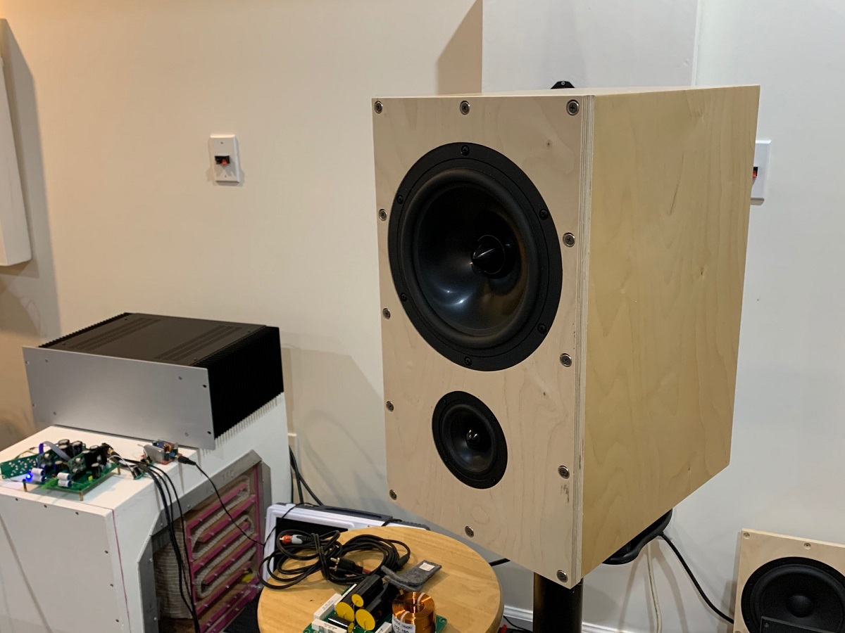
Vunce is reassembling his Alpha Nirvana and shared a great in progress photo. It really shows very nice clear details of how things can be mounted optimally in a cavernous 5U deluxe case. You can see the snubber boards and even the SLB has its own BJT snubber boards. I have those from the ABBB amp. But this looks like the ideal layout as wiring from soft start to trafo is very short, the SLB to amp is short too.

Attachments
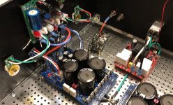
Vunce is reassembling his Alpha Nirvana and shared a great in progress photo. It really shows very nice clear details of how things can be mounted optimally in a cavernous 5U deluxe case. You can see the snubber boards and even the SLB has its own BJT snubber boards.
Sorry, X - why does the SLB need Snubber boards for its 5200 & 1943 transistors?
I thought these transistors could be bolted by themselves to their heatsink? 😕
Andy
It doesn’t need them, Vunce used them to reduce the wire stress/strain from flying lead mounting.
- Home
- Amplifiers
- Solid State
- Alpha Nirvana 39w 8ohm Class A Amp