And it does not react to the bias adjustment at all? Are you sure it's not oscillation that you're seeing? Maybe check the RC Zobel resistor, R41. Do all the resistors in the output stage check out OK? What replacements have you used for blown transistors, and where from?
Checked bias, both sides the same @ 9ma ish used tip41/42 and bd139/ 140 but one side is higher dc than the other...
So you mean output DC offset then? That's a different story. Two things coming to mind:
1. After catastrophic failure, that 47µ in the feedback ground leg is probably toast (shorted).
2. The input pair is a 2SA798, not exactly known as pure canned reliability. Two KSA992 joined at the emitter (not hip) and epoxied together (thermal coupling) make a good replacement.
TIP41/42 are a bit on the "slow and lumbering" side (fT 3 MHz vs. 8 MHz for the original types). I would definitely not run these at a measly 9 mA, which is even lower than factory spec (20 mA, or adjustment to 13 mV). Try adjusting bias to 26 mV (40 mA), assuming the heatsink is adequately sized.
Another potential problem: The original parts were in the D/E gain groups, i.e. beta = 60-200. While the OnSemi TIP41 looks like it would be OK, the Fairchild part never makes it much beyond 40-50.
BD139/140 are not the very definition of a speed demon either (fT 30-50 MHz, typ). I would prefer to run these at more than ~3 mA, too. Try R29/31 = 100R. You also have a chance of attaching these to the heatsink now for better thermal tracking.
I hope you have opted for some of the higher gain groups here, as the VAS only runs at 2 mA or so either. Changing that would take some reshuffling of part values, too.
If you want to do it right, you end up redesigning the whole power amp. It was one of these lower-power constructions that relied on the better-performing, higher beta transistors available when that's all you need.
Last edited:
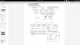
Download the service manual from "HIFI Engine" and go through the adjustment procedure of setting the bias current. This is done by actually measuring the idle "voltage" across the driver emitter resistors. If a resistor goes out of spec then the actuall idle current will be different as there is a different resistance now with the same setpoint (13mV) accross it.
If that is ok, then you will need to follow the schematic and start checking voltages as per the schematic to try and isolate the region/component that is faulty.
Also you can try and bypass the tone control section and see if both left and right channel power section boards are similar spec to each other.
Non- matched transistors (hfe) in current mirrors etc will cause a greater offset dc voltage on the speaker terminals (not to be confused with DC Bias). Maybe check your IC01-02 on the power boards (2sa798). You could replace those with a pair of match low signal transistors if needed as I think the 2sa798 may be difficult to find these days.
Keep at it and your persistance will pay off.
I still don't get it. How exactly are you measuring that - probe connection points, meter setting?No, there is high DC on the speaker output 100ma on one channel
You cannot literally "measure current" on a voltage output. It makes absolutely no sense whatsoever. (You are basically putting a short across the output.) You are going to get a current level defined by the ratio of (a) output DC offset voltage and (b) the sum of output resistance, test lead resistance and meter current sense resistor, as good ol' Mr. Ohm dictates. Pretty unpredictable, this.
If you are going to measure between the +/- output terminals, measure voltage. That's your output DC offset. Should usually be in the low tens of mV.
That said, if output DC offset is similar between channels but current differs, it's the channel with the low current that needs looking at - it may have an output fuse holder in need of cleaning or something, at least its output impedance would appear to be high.
Last edited:
"TIP41/42 are a bit on the "slow and lumbering" side (fT 3 MHz vs. 8 MHz for the original types). I would definitely not run these at a measly 9 mA, which is even lower than factory spec (20 mA, or adjustment to 13 mV) "
They are the ones I put in from farnell (not fleabay or aliexpress) and set it to 13mV and they run really nicely, no need to re-design the whole power amp") It sounds nice as is.
It sounds nice as is.
They are the ones I put in from farnell (not fleabay or aliexpress) and set it to 13mV and they run really nicely, no need to re-design the whole power amp
It sounds nice as is.Think the important part here is replace all electrolytic caps as well, if your holding onto it for yourself, I hear lots of people say, don't replace them unless its broke, But usually people that say that are people that can not do it them self and have to pay techs big money, but your only looking for problems with aging electrolytic caps with bad leaking (not physically but electrically) and bad ESR resistance causing all sorts of problems, mind you some vintage amps are a lot worse than this one, there is lots of space around the caps and they are not near heat sources, unlike my more modern Nad C370, and lots of modern equipment suffers from this from amps to TV's, its almost as if the manufactures have worked out exactly how many hours a 2000hrs cap will last at 40 degrees C before the warranty runs out.
Thats my rant over
Thats my rant over
Last edited:
- Status
- This old topic is closed. If you want to reopen this topic, contact a moderator using the "Report Post" button.
- Home
- Amplifiers
- Solid State
- sansui AU-2900