A dodgy diode would surely reduce the negative rail, not increase it? You have a voltage difference between the rails greater than the peak-to-peak voltage of the secondary apparently.
Have you checked the secondary ac voltage is correct?
Hi Mark
From my "non electronic technician" thought process and from looking at the schematics I was thinking that the diodes would separate the 62V from the 90V sections. When I follow the lines in the schematics there are places where the two different circuits are joined physically. Otherwise what keeps them apart?
I have checked the secondary AC voltage at the power supply with the boards disconnected and all looks okay. It is only when I connect the amplifier boards that the DC voltage on the -62V rail goes to -90V.
I repaired a NAD2200 some years back which a catastrophic failure in one of the power amps. Supply rails were quite uneven. The original cause for the failure was a dry joint on the power supply board centre tap return to the power transformer. I've seen others with the same suspect joints that haven't failed yet (but they will). Check this before you go further. Requires a bit of disassembly. Might save some heartache though.
I repaired a NAD2200 some years back which a catastrophic failure in one of the power amps. Supply rails were quite uneven. The original cause for the failure was a dry joint on the power supply board centre tap return to the power transformer. I've seen others with the same suspect joints that haven't failed yet (but they will). Check this before you go further. Requires a bit of disassembly. Might save some heartache though.
I have three voltages on the transformer, 27,5v ; 46v & 71v coloured yellow, red and orange respectively. On the 27,5V there is a grey earth and on the 46V and 71V there is a black wire. Are the centre taps the grey and black wires?
Connect one board at the time to find out which one is faulty.
Are Q323, Q327 and Q331 or equivalent on other board still ok? Or Q311? Is there any DC on the output at this point?
Hmmm, both boards are faulty. I had actually highlighted these transformers on the drawing because it looked to me like they could cause the problems i am having. When I started this project the left channel was good but the right was bad. I replaced all the caps and transistors on the right and when I powered up again the left was bad as well. I could be looking for a number of problems....
I Can't remember wire colors (it was quite a few years ago) but I do remember there was quite some disassembly to get to the pcb which had the transformer centre tap which was obviously machine soldered with the bare minimum of solder which had become a dry joint and caused mass destruction of one of the power amps. Even the IC which controls the speaker protection relay was shot. The other thing I remember was that at power up or down the power amp O/P DC swung wildly in normal operation. I connected a test speaker to the O/P before the relay and the cone nearly popped out of it's basket when I turned the amp off!!
Coincidentally I have a NAD 2200 about to hit my workbench shortly but I don't have it yet, otherwise I could give a more detailed description.
Coincidentally I have a NAD 2200 about to hit my workbench shortly but I don't have it yet, otherwise I could give a more detailed description.
I have three voltages on the transformer, 27,5v ; 46v & 71v coloured yellow, red and orange respectively. On the 27,5V there is a grey earth and on the 46V and 71V there is a black wire. Are the centre taps the grey and black wires?
Checked the main power supply tonight. With both boards completely disconnected the DC power out of the rectifiers is correct. I then tried connecting left and right channel amp boards one by one and in each case the -60V rail goes up to -90V, the same with both boards connected at the same time.
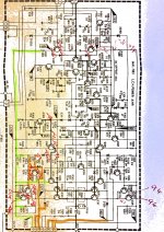
I have done a bit of checking around the board where I thought it may point towards a problem but nothing conclusive. I have marked up the schematic on the attached. Left and right boards are the same.
Any advice on where to look next and what to look for would be appreciated.
I have done a bit of checking around the board where I thought it may point towards a problem but nothing conclusive. I have marked up the schematic on the attached. Left and right boards are the same.
Any advice on where to look next and what to look for would be appreciated.
Attachments
Amp is a power envelop model, appears that the outer high voltage rail is finding its
way into the low voltage rail, probably due to failed silicon. Same fault on both channels
which is unlucky. Had a look at the voltage measurements, voltages around Q303 and Q307 look suspect, downstream voltages may be caused by this.
Measure Q303 b/c/e voltages to GND/chassis. Repeat for Q307. Measure to first decimal
point, need to check Vbe of both. possibly a collector-emitter short on either these Q's.
Suggest also diode check these transistors with amp powered off/unplugged.
Have you checked that the transformer centre tap connection to ground is intact (F13 on the rectifier pcb). This was the route cause of the blow up on a 2200 I repaired some years back. It caused the plus and minus supplies to become unbalanced when they were connected to the Power Amp modules. They measured o/k with no load ie power stages disconnected but unbalanced and varying when power amps connected. As I stated earlier it was caused by dry joints due to a poor machine soldering process (minimal solder, high peak currents etc).
Have you checked that the transformer centre tap connection to ground is intact (F13 on the rectifier pcb). This was the route cause of the blow up on a 2200 I repaired some years back. It caused the plus and minus supplies to become unbalanced when they were connected to the Power Amp modules. They measured o/k with no load ie power stages disconnected but unbalanced and varying when power amps connected. As I stated earlier it was caused by dry joints due to a poor machine soldering process (minimal solder, high peak currents etc).
I checked the connections from the transformer to the pins before the diodes. All looks good. Should I resolder them to be sure perhaps? Just thinking now... I haven't checked the pin to earth so will do that tonight. I also checked the inputs and outputs to both diode rectifiers with the amp boards disconnected and all looked good, the relays clicked in as well so I'm guessing the protection circuit is okay. I did not open up the transformer to check the internal connections as it appears to be sealed up. Is that something I should check as well?
Thanks.
Certainly check the transformer GND connection, a bad earth would stuff up the voltage
measurements. That said, I think the transformer is ok. When the power amps are
disconnected you get the correct voltages on the pos/neg rails of the power supply.
No need to check transformer internals (fuse only?), however any smoke/load buzz/char
marks would be a red flag.
measurements. That said, I think the transformer is ok. When the power amps are
disconnected you get the correct voltages on the pos/neg rails of the power supply.
No need to check transformer internals (fuse only?), however any smoke/load buzz/char
marks would be a red flag.
Amp is a power envelop model, appears that the outer high voltage rail is finding its
way into the low voltage rail, probably due to failed silicon. Same fault on both channels
which is unlucky. Had a look at the voltage measurements, voltages around Q303 and Q307 look suspect, downstream voltages may be caused by this.
Measure Q303 b/c/e voltages to GND/chassis. Repeat for Q307. Measure to first decimal
point, need to check Vbe of both. possibly a collector-emitter short on either these Q's.
Suggest also diode check these transistors with amp powered off/unplugged.
Q303 b/c/e -94.4/-95/-95 b/e 0.69
Q307 -95.1/-95.8/-94.9 b/e 0.51
Out of circuit checked out good.
Have you checked that the transformer centre tap connection to ground is intact (F13 on the rectifier pcb). This was the route cause of the blow up on a 2200 I repaired some years back. It caused the plus and minus supplies to become unbalanced when they were connected to the Power Amp modules. They measured o/k with no load ie power stages disconnected but unbalanced and varying when power amps connected. As I stated earlier it was caused by dry joints due to a poor machine soldering process (minimal solder, high peak currents etc).
Earth seems good, less than 1 ohm from the wire to the frame.
Oh its class-G with two sets of rails. Suspect the commutating diodes (D329 / D331)?
They checked out okay, also did 330 and 332
With the dmm in diode test, do you have connectivity between the -92 and -65 volt connectors both ways? Could be some power transistors failing. There is also a diode on the input of the -65 volt connector. Maybe for safety reasons? Are those ok?
Not sure what you mean by "connectors", where am i testing in the circuit? Could you identify the components by their number?
- Status
- This old topic is closed. If you want to reopen this topic, contact a moderator using the "Report Post" button.
- Home
- Amplifiers
- Solid State
- Nad 2200 Recap and Repair