Hi all,
Ive just joined up, seen some really useful stuff on here whilst Ive been trying to figure out what might be wrong with this Amp.
This amp means quite a lot to me as it was my late Father's and I remember him buying it (along with matching components) in around 1984/5. Ive been pestering my Mum for it and she finally agreed last week, so I collected it and eagerly set it up at home, connected to my newly installed cieling speakers and.....no sound!
Now I cant be sure the last time this was actually used, it has sat in my Mum's cupboard connected but switched off for many years now.
I always recalled that after a few seconds it would emit a click sound before the speakers would engage (a relay I guess).
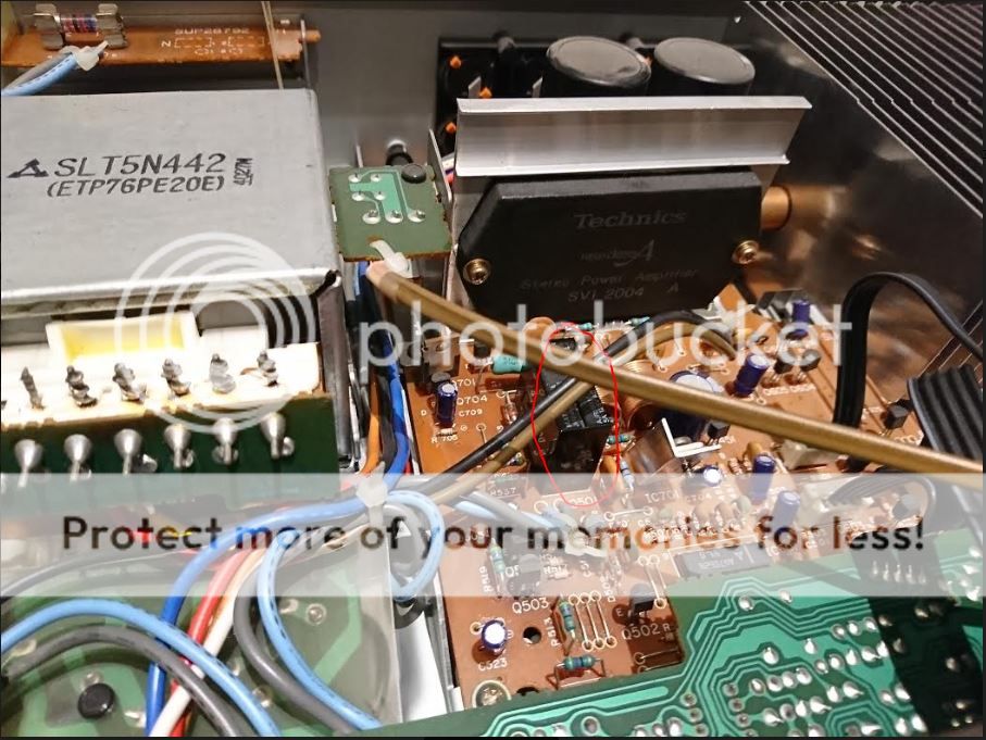
It has never been messed with, never even opened up before and is clean and hardly any dust inside. Has the SVI 2004 A Amp IC
So when I switch it on, the amber light for the saftey operation flashes for about 5 seconds and then stays solid. According to the user manual this is normal, ie no fault detected.
about 5 seconds or so later, the green computer drive light goes green.
So it all looks like should be working, I know the input selectors seem working and I can pass the signal through the technics graphic equalizer as I can see the bars moving.
So there should be an output, but nothing from any of the 4 speaker ports regardless of any button settings.
Any ideas?
Im hoping it might be something simple, Id like to fix it or get it fixed if possible and if it's worth it, not just because I think it always was and probably still is a good amp, but also because it has sentimental value.
Any help would be much appreciated! I will attach a photo of it and the inside once ive downloaded the pics from my phone, as I opened it up to check for anything obvious. Both fuses are OK and I cant see any obvious signs of loose components or leaking capacitors.
thanks
Aaron
Ive just joined up, seen some really useful stuff on here whilst Ive been trying to figure out what might be wrong with this Amp.
This amp means quite a lot to me as it was my late Father's and I remember him buying it (along with matching components) in around 1984/5. Ive been pestering my Mum for it and she finally agreed last week, so I collected it and eagerly set it up at home, connected to my newly installed cieling speakers and.....no sound!
Now I cant be sure the last time this was actually used, it has sat in my Mum's cupboard connected but switched off for many years now.
I always recalled that after a few seconds it would emit a click sound before the speakers would engage (a relay I guess).
It has never been messed with, never even opened up before and is clean and hardly any dust inside. Has the SVI 2004 A Amp IC
So when I switch it on, the amber light for the saftey operation flashes for about 5 seconds and then stays solid. According to the user manual this is normal, ie no fault detected.
about 5 seconds or so later, the green computer drive light goes green.
So it all looks like should be working, I know the input selectors seem working and I can pass the signal through the technics graphic equalizer as I can see the bars moving.
So there should be an output, but nothing from any of the 4 speaker ports regardless of any button settings.
Any ideas?
Im hoping it might be something simple, Id like to fix it or get it fixed if possible and if it's worth it, not just because I think it always was and probably still is a good amp, but also because it has sentimental value.
Any help would be much appreciated! I will attach a photo of it and the inside once ive downloaded the pics from my phone, as I opened it up to check for anything obvious. Both fuses are OK and I cant see any obvious signs of loose components or leaking capacitors.
thanks
Aaron
No click = relays not engaging = no output. Since you say it sat unused for several years, it could be as simple as a dead electrolytic cap in the relay driver circuit... or just a bad solder joint that got upset when moving the unit. Further investigation with a multimeter and a keen eye will be required, as well as studying the service manual.
What's your experience level in terms of electronics DIY or repair? Do you have a decent smallish soldering iron or station and a multimeter? Can you read schematics?
What's your experience level in terms of electronics DIY or repair? Do you have a decent smallish soldering iron or station and a multimeter? Can you read schematics?
Perfect, thanks I was hoping it might be something simpler like the relay it's self rather than the main IC.
thanks for the link to the service manual, I'll register on that site and download it")
I do have a multimeter and am reasonably OK following schematics, I have a soldering iron but i'm not too good with it to be honest, it's quite a while since I did any neat soldering.
The Relay - seems like it has a top cover or something, is this removable? I can wiggle it but not seem to pull it off.
Im still figuring out how to insert an image, I guess they have to be hosted first in something like photobox?
thanks for the link to the service manual, I'll register on that site and download it
I do have a multimeter and am reasonably OK following schematics, I have a soldering iron but i'm not too good with it to be honest, it's quite a while since I did any neat soldering.
The Relay - seems like it has a top cover or something, is this removable? I can wiggle it but not seem to pull it off.
Im still figuring out how to insert an image, I guess they have to be hosted first in something like photobox?
No, no need to host photos on other server, that's not a good option. There is plenty of threads with blank photo as the hosting server no longer provides photo.
When you write post, insted of quick reply, hit go advanced, that will open window with attach images, browse from your computer, select, upload...its easy.
SVI beat me...
When you write post, insted of quick reply, hit go advanced, that will open window with attach images, browse from your computer, select, upload...its easy.
SVI beat me...


I'll have a look and let you know.
is there any way for me to get at the relay internals without taking the whole unit apart and taking out that bottom circuit board and desoldering it?
but I'll do the measurment checks beforehand as suggested in the thread.
I have tried tapping last night but it had no effect.
thanks
Aaron
is there any way for me to get at the relay internals without taking the whole unit apart and taking out that bottom circuit board and desoldering it?
but I'll do the measurment checks beforehand as suggested in the thread.
I have tried tapping last night but it had no effect.
thanks
Aaron
Opening the relay won’t achieve a lot as it’s most likely the coil wire broken at the terminal... you can squeeze firmly at the corners and it will unclip on the long sides.
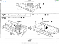
Don’t need to pull main board out as such - undo screw at front corner of main board, and the screw at heatsink support (see pic) then the 4 screws under bottom panel
Do also check joints on Q608 (relay drive)
Don’t need to pull main board out as such - undo screw at front corner of main board, and the screw at heatsink support (see pic) then the 4 screws under bottom panel
Do also check joints on Q608 (relay drive)
Attachments
Great! thanks, I also have the service manual downloaded and that's a massive help!
Im not with the unit at the moment, so I'll have a fiddle this evening.
Just one more question though - if I were to plug some headphones into the jack, would I expect to get sound even if the relay wasnt working? or does that control the output to headphones also?
cheers
Aaron
Im not with the unit at the moment, so I'll have a fiddle this evening.
Just one more question though - if I were to plug some headphones into the jack, would I expect to get sound even if the relay wasnt working? or does that control the output to headphones also?
cheers
Aaron
Hi, I have exactly the same problem, plus, probably, several more. Green liight is on, relay is not. I have changed several electrolyths, as well both 3,3 25v, which actually were 2,5v. C710 c709, then changed ic701, as it was not providing stable 5v. Still something wrong. Removed the cap of relay, tested it, as far i remember it works from something ~115v. Still nothing. One thing which is strange on ic502 leg 7-10 is constant -52 volts. That forced me to change q606 without results. I am now concerned if i have not burned ic502.. any coments?
One thing which is strange on ic502 leg 7-10 is constant -52 volts. That forced me to change q606 without results. I am now concerned if i have not burned ic502.. any coments?
In this amp the manual is incorrect... near on -50 or -43v is no load condition
The -V is fed from a digital transistor UN4211 (Q606) under overload, the SVI will pull up the -V towards ground, which turns on Q606, triggering overload detector feed to IC601
Thank you for response. As far as i remember all pins on ic601 are more or less correct voltage, will check pin 12 valtage one more time. As well as R630.If [Safety Operation] is steady and [Auto/computer drive] is lit - there is no overload or fault.
IC 601 pin 12 should be 2.8V or higher, which feeds Q608 that turns relay on.
R630 (2W 560 ohm) supplies power to relay
Last edited:
- Status
- This old topic is closed. If you want to reopen this topic, contact a moderator using the "Report Post" button.
- Home
- Amplifiers
- Solid State
- Technics SU-V4X problem - no click from relay but indicator lights OK