Result! I have a click! so there's life in the old dog yet!
the impedance selector switch is iffy. I fiddled with it until I had a solid continuity in the out position (8 ohm setting) on both output pins on the underside of the circuitboard and then powered it up. click of relay as soon as the amber safety light went solid.
I am thinking when I move it back in position and connect speakers it likely the switch contacts will have disconnected again so will need fettling. But for now that will do me but if its troublesome ongoing I'll replace it or bypass it.
(ive not tested it with speakers hooked up yet but will do tomorrow).
seems like a bit of a design flaw that such a small inconspicuous black button on the back of the amp could be responsible for causing total lack of power to the amp circuits! I wonder how many perfectly good amps have been chucked out for similar issue
anyway, glad that's solved and without too much drama and zero cost
Good luck with yours Breidonis…...could be something similar
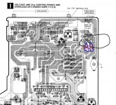
for clarity - circled red the output pins paired with the 2 different voltage inputs from the transformer (+-38v or +-32v). In black is the bypass that could be done if the switch was removed (or at least the other 32v wires disconnected and made safe) or the other way around depending on which impedence setting is desired

Last edited:
in my case Ive now got myself confused. I removed the bottom panel. testing continuity (power lead disconnected) I find that all wire inputs 701, 702, 703, 704 have continuity to each other and to ground and so do all connections on the transformer. this cant be right can it? so now I don't want to plug it back in incase something is shorted to ground somewhere......or is this normal that all windings eventually lead to ground and therefore each other? but resistance is also zero
i tested 701,702,703,704 all have continuity to each other and to ground.
I found voltage on PCB 701 and 702 is 41.1v, on 703, 704 is 33.3v, acc to schematics should be opposite?
on 708 13.3v,
on 707 0,0v
Result! I have a click! so there's life in the old dog yet!
the impedance selector switch is iffy. I fiddled with it until I had a solid continuity in the out position (8 ohm setting) on both output pins on the underside of the circuitboard and then powered it up. click of relay as soon as the amber safety light went solid.
I am thinking when I move it back in position and connect speakers it likely the switch contacts will have disconnected again so will need fettling. But for now that will do me but if its troublesome ongoing I'll replace it or bypass it.
(ive not tested it with speakers hooked up yet but will do tomorrow).
seems like a bit of a design flaw that such a small inconspicuous black button on the back of the amp could be responsible for causing total lack of power to the amp circuits! I wonder how many perfectly good amps have been chucked out for similar issue
anyway, glad that's solved and without too much drama and zero cost
Good luck with yours Breidonis…...could be something similar
for clarity - circled red the output pins paired with the 2 different voltage inputs from the transformer (+-38v or +-32v). In black is the bypass that could be done if the switch was removed (or at least the other 32v wires disconnected and made safe) or the other way around depending on which impedence setting is desired
View attachment 728054
lucky you!
Sweet bro.... well I have 30 V4X amps none have had an impedance sw fault, but get how it could happen.... did your father live near the beach.... amps that live near beaches develop much more tarnish on switch contacts.... had several SU-V8 amps riddled with input selector switch faults due to that
SVI2004A, how do you think, can it be faulty relay? out of your 30 V4X amps was an option with faulty relay? do not have any other idea.
actually my first test was relay, i took it out, tested impedance, as it was something, not short and not infinitive resistance, i just simply soldered in back.
actually my first test was relay, i took it out, tested impedance, as it was something, not short and not infinitive resistance, i just simply soldered in back.
Briedonis is there 50V at R630?
On one side of R630 is ~52v, and it is 28.6v on the other side R630 to the relay pin.
@ Briedonis IMO that sounds spot on then...duff relay if there's nothing the other side of it.
but check you are getting correct voltage into Q608 from IC 601 pin 12. You might have already checked that but just in case. also check zener diode D603 isnt faulty as that could possibly stop the relay working properly I guess.
good luck....im off now to hook mine back up and see it will now drive my speakers
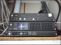
@SVI2004A no not by the sea at all. South London all it's life! The Amp spent the first 20 years sitting in one audio cabinet, then moved once with my mother to another house down the same road, and then sat there in a different cabinet until a few weeks ago, and barely used. So a bit unexplained because its so clean inside barely any dust or anything, given its age.
Last edited:
@ Briedonis IMO that sounds spot on then...duff relay if there's nothing the other side of it.
but check you are getting correct voltage into Q608 from IC 601 pin 12. You might have already checked that but just in case. also check zener diode D603 isnt faulty as that could possibly stop the relay working properly I guess.
good luck....im off now to hook mine back up and see it will now drive my speakers
e.
it is 2.8V on pin 12 IC 601.
even checked diode D603 with multimeter, looks like ok.
cannot find specification for relay, what voltage is needed to start it. suppose ~25v. will take it out and test it this evening.
otherwise have no idea what can be wrong.
it's the transistor Q608 that switches it on. So as you have R630 correct voltage around 28v and IC601 sending switch on signal all is good there.
measure leg B on Q608, I got around 0.66v. if you do, then all good there. That means the transistor should be switching on the relay.
Measure the other legs on Q608, one should be the same voltage roughly as you see on the lower side of the R630 ie 28v ish. If not, then there's two possibilities. Either the Q608 is faulty (or not enough voltage at B to turn it on so could be a duff resistor between IC601 and Q608) OR your relay is broken.
If you do have a voltage, then in theory power is running through the relay but the output isnt engaging. so again - duff relay.
I must admit, I dont know exactly what happens from the relay output to engage the speakers, that dotted line on the schematic seems to lead to other switches. Worth also checking resistor R631
for me though - all good, sound from my system at last ! so im happy

Last edited:
it's the transistor Q608 that switches it on. So as you have R630 correct voltage around 28v and IC601 sending switch on signal all is good there.
measure leg B on Q608, I got around 0.66v. if you do, then all good there. That means the transistor should be switching on the relay.
Measure the other legs on Q608, one should be the same voltage roughly as you see on the lower side of the R630 ie 28v ish. If not, then there's two possibilities. Either the Q608 is faulty (or not enough voltage at B to turn it on so could be a duff resistor between IC601 and Q608) OR your relay is broken.
If you do have a voltage, then in theory power is running through the relay but the output isnt engaging. so again - duff relay.
I must admit, I dont know exactly what happens from the relay output to engage the speakers, that dotted line on the schematic seems to lead to other switches. Worth also checking resistor R631
for me though - all good, sound from my system at last ! so im happy
View attachment 728170
it is 0,7V on leg B, 0,7v on leg C, it is 0,0v on emitter on Q608
i will test R631 and diode D603. also relay.
Sounds like the relay driver is working, and moreover, it seems that some current is flowing through it.it is 0,7V on leg B, 0,7v on leg C, it is 0,0v on emitter on Q608
Only two options remaining - relay supply voltage is too low for it to engage, or it's mechanically blocked. Well, yeah, could be a shorted diode as well, but I can't remember hearing of them failing in this application.
Sounds like the relay driver is working, and moreover, it seems that some current is flowing through it.
Only two options remaining - relay supply voltage is too low for it to engage, or it's mechanically blocked. Well, yeah, could be a shorted diode as well, but I can't remember hearing of them failing in this application.
If relay has mechanical defect, in theory if i push it down and close contacts, signal should appear on speaker channels? Is it safe to try?
- Status
- This old topic is closed. If you want to reopen this topic, contact a moderator using the "Report Post" button.
- Home
- Amplifiers
- Solid State
- Technics SU-V4X problem - no click from relay but indicator lights OK
