Hi Folks,
As this is my second posting on these forums it will be ignored.
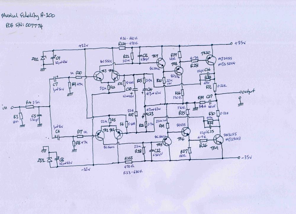
Ok, i've got one of these old bipolar tranny amps. i bought it with a fault - a roughly continuous >200kHz ring on one channel.
i've stripped and re-built it, replacing all electrolytics for +104°C versions, replacing all bipolars with hFE matched pairs or quads. Still it rings.
"Yes", you all say, "throw it away and buy a decent amp. Before it burns your house down". Yes good, however i'm a fan of the designer of this amp's work.
Anyway, tracing out the circuit diagram of the power amp section i got this:
Any thoughts folks ?
xx.
As this is my second posting on these forums it will be ignored.
Ok, i've got one of these old bipolar tranny amps. i bought it with a fault - a roughly continuous >200kHz ring on one channel.
i've stripped and re-built it, replacing all electrolytics for +104°C versions, replacing all bipolars with hFE matched pairs or quads. Still it rings.
"Yes", you all say, "throw it away and buy a decent amp. Before it burns your house down". Yes good, however i'm a fan of the designer of this amp's work.
Anyway, tracing out the circuit diagram of the power amp section i got this:
Any thoughts folks ?
xx.
Hi Redbeard,
Didn't see you first post. Welcome to DIYAudio!
You did a good job so far. The schematic is too small for me to make it out properly. Check the resistor and capacitor that make up the output zobel network. If either goes open the amplifier will be unstable. This network goes from the output to ground.
-Chris
Member
Joined 2009
Paid Member
this amp looks quite similar to my TGM7 amplifier - it was an extremely high gain bandwidth amp that took some effort to tame in terms of oscillations. At 200kHz it could well be instability from the global feedback loop so I'd check the compensation caps (like said already, hard to see the low resolution image) of which there appear to be several, including those on the base-collector of the drivers. Wiring is key too, any output signal currents invading the input signal ground will give big trouble.
Just for test purpose try increase C32 like x10 or more. Same goes for its counterpart C22 (? I can't see values properly). So if it's a compensation issue this is supposed to cure oscilations. Then step by step try lower and lower values (keep these caps closely matched) to find the safe limit.
Of course, bad contact could also be the cause.
Of course, bad contact could also be the cause.
Last edited:
Hi Folks,
Thank you all for your welcome and positive comments.
By "lag caps", you mean the ones in parallel with a resistor (collector of both output transistors to base of input stage long-tail pair, and +ve and -ve supplies across collector load resistors of other side of long-tailed pair ?
i've attempted to post another copy of the circuit, this one from spice, to be a bit more legible. When i've swapped the capacitors and had a play about i'll report back.
Cheers,
Xx.
Thank you all for your welcome and positive comments.
An externally hosted image should be here but it was not working when we last tested it.
By "lag caps", you mean the ones in parallel with a resistor (collector of both output transistors to base of input stage long-tail pair, and +ve and -ve supplies across collector load resistors of other side of long-tailed pair ?
i've attempted to post another copy of the circuit, this one from spice, to be a bit more legible. When i've swapped the capacitors and had a play about i'll report back.
Cheers,
Xx.
 Use the advanced answering attachments management menu to upload it here. It does not show even with right click open link in new tab as you posted it now.
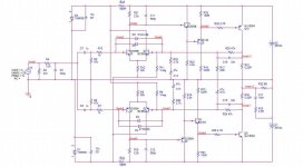
With power amps, especially ones that are going out into the world away from my setup, I always use ferrites on the inputs to help prevent hf issues. Kind of an afterthought, bandaid but it has helped it seems.
Also have a look at the hafler schematics and look at the zobel used there, it’s a twice redundant setup that works well.
Also have a look at the hafler schematics and look at the zobel used there, it’s a twice redundant setup that works well.
Thank you Zen Mod, i found Mark Hennessy's excellent web page before buying the amp. It does indeed contain an awful lot of useful information.
Chip_mk, ok, i started with the wrong ones - C15 and C16. Upping these by a factor of 10 has stopped the HF oscillation. This week (when i have time) i'll gradually reduce them until ringing starts again then up their values as you suggest. Or would i be better starting with C11 and C12 ?
Cheers Folks,
xx.
'Phew,
My humble apologies for not having posted for a while - they've been keeping me too busy at w**k to play with the old A-100.
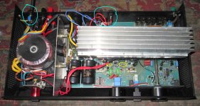
Attached photograph shows the state of play at the moment.
Ok, the story so far - i changed C15 and C16 for 10 x value (i.e. 220pF) and the oscillation stopped. However, i'd also changes the two "bias" resistors (R6, R11) from the fitted 5.6MΩ to 2.4MΩ to see what that would happen.
The amp sounded great, but thermally shut down after about 20 minutes. Hardly surprising as i was biasing it hot and the attached heatsink (the silver thing scrounged from the scrap pile at w**k) only allows dissipation upwards, isn't of of as great an area as the proper lid, doesn't allow the fan to properly channel through the inverted "U" section as it should &c.
Last change was fitting "Vero" forked pins to the mounting points for R6,11 and C15, 16 to allow for easy component changes from above.
R6 and R11 were swapped back to their original values, C15 and C16 were changed for 100pF.
Last run, the left channel oscillated and sounded rotten but the right channel sounded alright, so i swapped C15 and C16 for 150pF.
Prodding showed that my soldering is dodgy. Back to the soldering board ;o)
On the photograph, the left-channel parts under investigation are circled yellow and green. Chassis modifications i have made are circled pale blue. +VB and -VB fuses, thicker mains lead with earth, earth-lift switch (closed, the chassis is earthed, open the chassis is earthed through 200Ω).
Some thoughts on the A-100.
"The A-100 is biased less into class 'A' than the A-1": Considering the +/- 35Vdc rails against the A-1's +/- 25V (or less ?) rails, maybe so in terms of rail-to-rail operation or maybe not in terms of actual operation.
In terms of servicing, it's the Devil's own job. A hatch underneath exposing the track side of the PCB would have made all this mucking about easier.
Design flaws: The circuit of the A-100 is practically taken straight from the A-1. As a result the +/- 12Vdc rails (for the "tails" of the LTP input stage and also for powering the drive op-amp) are really cooking. In the A-1 (running off +/- 25Vdc or so), R13 and R14 may be right but in the A-100 the resistance values are far too low.
The "tail" of the long-tailed pairs draws very little current, almost all the current through R13 and R14 has to be dumped bu the zeners. In mine i've doubled the 680Ω's to 1200Ω and they still cook. Next step is 2.4kΩ.
Thank you all, i know i'm just talking to myself. Thank you for your patience.
Neil Xx.
My humble apologies for not having posted for a while - they've been keeping me too busy at w**k to play with the old A-100.
Attached photograph shows the state of play at the moment.
Ok, the story so far - i changed C15 and C16 for 10 x value (i.e. 220pF) and the oscillation stopped. However, i'd also changes the two "bias" resistors (R6, R11) from the fitted 5.6MΩ to 2.4MΩ to see what that would happen.
The amp sounded great, but thermally shut down after about 20 minutes. Hardly surprising as i was biasing it hot and the attached heatsink (the silver thing scrounged from the scrap pile at w**k) only allows dissipation upwards, isn't of of as great an area as the proper lid, doesn't allow the fan to properly channel through the inverted "U" section as it should &c.
Last change was fitting "Vero" forked pins to the mounting points for R6,11 and C15, 16 to allow for easy component changes from above.
R6 and R11 were swapped back to their original values, C15 and C16 were changed for 100pF.
Last run, the left channel oscillated and sounded rotten but the right channel sounded alright, so i swapped C15 and C16 for 150pF.
Prodding showed that my soldering is dodgy. Back to the soldering board ;o)
On the photograph, the left-channel parts under investigation are circled yellow and green. Chassis modifications i have made are circled pale blue. +VB and -VB fuses, thicker mains lead with earth, earth-lift switch (closed, the chassis is earthed, open the chassis is earthed through 200Ω).
Some thoughts on the A-100.
"The A-100 is biased less into class 'A' than the A-1": Considering the +/- 35Vdc rails against the A-1's +/- 25V (or less ?) rails, maybe so in terms of rail-to-rail operation or maybe not in terms of actual operation.
In terms of servicing, it's the Devil's own job. A hatch underneath exposing the track side of the PCB would have made all this mucking about easier.
Design flaws: The circuit of the A-100 is practically taken straight from the A-1. As a result the +/- 12Vdc rails (for the "tails" of the LTP input stage and also for powering the drive op-amp) are really cooking. In the A-1 (running off +/- 25Vdc or so), R13 and R14 may be right but in the A-100 the resistance values are far too low.
The "tail" of the long-tailed pairs draws very little current, almost all the current through R13 and R14 has to be dumped bu the zeners. In mine i've doubled the 680Ω's to 1200Ω and they still cook. Next step is 2.4kΩ.
Thank you all, i know i'm just talking to myself. Thank you for your patience.
Neil Xx.
Attachments
 TRANSLATION
Tenga en cuenta que este es un foro en inglésPut value of the components as designed by Tim Paravicini and you will not have problems
Thank you Carmelo86 and AllenB for your response and your translation.
Carmelo86, the reason for not fitting the value of components of Tim de Parivicini's design is the only record of the component values is from the amplifier i stripped to trace it's circuit diagram. As far as i know, no other diagram exists on the internet.
Using the original component values will simply reproduce the problems i found earlier in this topic.
Part of the problem is that whilst Tim designed the A-1, i do not know if he was involved in the update to the A-100. Had he been, faults such as R13/113, R14/114, ZD1 and ZD2 burning the PCB would never have occurred.
You must also remember that very few people had access to SPICE techniques back in the early-to-mid 1980's when these amplifiers were made.
Full transcription of original circuit is attached.
Attachments
Hello
I am saying this in a nice way .. unless you are a qualified experienced audio design engineer (which you may well be ) put all the values back to base condition as per the original design. If you are changing component values have you the calculations to backup and validate the changes you are making ? otherwise you are just stabbing in the dark so to speak .. But sometimes this can work for the lucky few but when they get a improvement they are normally not sure why")
I am saying this in a nice way .. unless you are a qualified experienced audio design engineer (which you may well be ) put all the values back to base condition as per the original design. If you are changing component values have you the calculations to backup and validate the changes you are making ? otherwise you are just stabbing in the dark so to speak .. But sometimes this can work for the lucky few but when they get a improvement they are normally not sure why
- Home
- Amplifiers
- Solid State
- New Musical Fidelity A-100 nonsense.