Decades ago there was no earth installation in the houses, so you can disconnect the earth to check if it sounds better.
I think there are still countries that have not implemented it or their inhabitants do not install it!
It didn't made any diffirence for the hum, so ground loop breaker won't help either? Tried also 10r resistor on wire between signal returns, didn't help. Only thing so far that makes hum go away is disconnecting one rca. I remember having the same problem with Aleph 5 dual monos. Connected star grounds together with thick wire made it quiet back then.
Vince and the others:
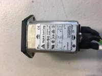
Schaffner RF/EMI filter inlet: FN 9244B 1A or 3A
[PDF] FN 9244
An externally hosted image should be here but it was not working when we last tested it.
An externally hosted image should be here but it was not working when we last tested it.
B: medical
Good call Maty!!
I removed a similar AC module from a recycled piece of electronics and hooked it up to my Alpha. With it installed the LED lights/dimmer noise was greatly reduced, not totally eliminated but MUCH better than without it.
Thanks for the tip 🙂
Cheers,
Vunce
Attachments


I have a lot of Schaffner RF/EMI (they have the best specs/graphs) and Würth RF 150 kHz ferrites in my house.
With my Yamaha: one RF/EMI filter + RF ferrite.
With my Marantz: two RF/EMI filter + RF ferrite.
With the RF ferrite I managed to reach the maximum attenuation without the sound degrading.
And a lot of DC Blockers too.
With Yamaha: DCB + DCBx2 = DCBx3 all with Big EPCOS
With Marantz: DCB (Mundorf) + DCBx4 (EPCOS) = DCBx5
They eliminates "ripple" from mains too.
Pictures: go to Images: dc blocker maty - Google Search
Yes, I have "tons" of RF/EMI and DC in my house. And some days I have almost 240 Vac too.
Last edited:
Main floor here every wall socket has earth, first floor bathroom has earth too but bedrooms don't have earth. House was built according to all regulations here in 1992, not very very old, but not new 🙂
My first DIY Schaffner RF/EMI cable, without earth:
An externally hosted image should be here but it was not working when we last tested it.
An externally hosted image should be here but it was not working when we last tested it.
By the way, the better IEC C14 connector are the Schurter, I love them.
An externally hosted image should be here but it was not working when we last tested it.
Last edited:
Thanks for your help Maty, now I nailed it! Just lifted 0V before amp board with 10r resistor and thats it 🙂 happy again!
Safety First
ATTENTION!!!
Don't remove safety earth connection!
Never.
Don't put at risk your life
ATTENTION!!!
Don't remove safety earth connection!
Never.
Don't put at risk your life
ATTENTION!!!
Don't remove safety earth connection!
Never.
Don't put at risk your life
5 sec test under controlled enviroment and remote power connection didn't killed anyone this time, but you are absolutely correct and right!
Edit: I did it because I wanted to figure out that do I need ground loop breaker. It seems I don't, so safety earth can now be connected without anything extra built to it.
Last edited:
Hi Vunce,
Nice noise/hum hunting that you did.
Can you specify some more about the “Hum Buster” 15R that you implemented ?
Did you add a 15R ground lift for the input stage + fb (RCA gnd, C101, R102, C111, C115) ?
I found the articles : "Advanced Grounding Guruship" and "The library of grounding problems"
Regards,
Danny
Hi Danny,
Yes, that’s the ‘guide’ I referenced.
I connected the HBR between the signal gnd pad and 0V input pad on the backside of the alpha board.
My chassis has basically 3 individual metal panels that I think will need to be linked together in order for all the precautions to work properly. The input RF filter capacitor mounted at the rca input will not work unless the metal rear panel is connected to the metal base that has chassis earth ground bolt? Correct?
ATTENTION!!!
Don't remove safety earth connection!
Never.
Don't put at risk your life
5 sec test under controlled enviroment and remote power connection didn't killed anyone this time, but you are absolutely correct and right!
Edit: I did it because I wanted to figure out that do I need ground loop breaker. It seems I don't, so safety earth can now be connected without anything extra built to it.
Do it for instant test only,under full controlling conditions.😉
The usual cases of electrocution at home are usually in the bathroom: bathtub with water and hairdryer.Don't put at risk your life
Well, a class A amplifier is almost a little hairdryer by the amount of current 😀
1500 watts at 230 Vac -> 7 A. 115 Vac -> 14 A.
150 watts at 230 Vac -> 0.7 A. 115 Vac -> 1.4 A.
Last edited:
I connected the HBR between the signal gnd pad and 0V input pad on the backside of the alpha board.
I'm missing something here, on my Alpha20 PCB the "IN" signal pad gnd is already connected with the 0V pad.
Yes, all the metal panels and also the heatsinks need to be connected, check with DMM.
Regards,
Danny
Thanks for your help Maty, now I nailed it! Just lifted 0V before amp board with 10r resistor and thats it 🙂 happy again!
Hello Juntuin,
Great news that you got your Alpha hum knocked down! Where did you install the 10r resistor?
By the way, ALL should look the power inlet at AV Receivers.
An example:
[URL="https://www.pioneerelectronics.com/StaticFiles/Custom%20Install/Detailed%20Product%20Information/AV%20Receivers/SC-65_Back.jpg"]https://www.pioneerelectronics.com/StaticFiles/Custom%20Install/Detailed%20Product%20Information/AV%20Receivers/SC-65_Back.jpg[/URL]
Off course, the ALPHA should have a [B]star ground[/B] [I](circuits -> case)[/I].
The 10R ground lift/hum buster resistor is already built into the B.B. thankfully. You want to lift everything except power ground and ground for LTP smoothing cap.
Hello Juntuin,
Great news that you got your Alpha hum knocked down! Where did you install the 10r resistor?
It's really a pleasure to listen it now! Conventional CRC supply seems to work much better with this application.
I disconnected 0v wire from PCB and placed 10r between 0V from PSU and PCB. So whole amp's PCB got lifted 0V. So did it much like you, but you lifted only signal ground?
Setup now;
12 x 22 000uF caps in CRCCRC - configuration, 500VA 2x20V toroid, higher "original" bias (1,9A if remember correctly?). Only modification is lifted 0V from boards and ground loops are gone. Amp is now almost dead quiet again with 96db/w/m speakers. Sounding really nice!
Oh, btw; I tried to lift only signal ground at first, it didn't had any effect?!
Last edited:
Thanks for your help Maty, now I nailed it! Just lifted 0V before amp board with 10r resistor and thats it 🙂 happy again!
Hi Juntuin,
You lifted the whole pcb ground with 10R?
Also the speaker return or did you connect the speaker return at the PS gnd ?
Normally only the signal pad should be lifted,
the C103 decoupling cap and speaker return should be connected to gnd PS, not via 10r lift.
Regards,
Danny
Hi Juntuin,
You lifted the whole pcb ground with 10R?
Also the speaker return or did you connect the speaker return at the PS gnd ?
Normally only the signal pad should be lifted,
the C103 decoupling cap and speaker return should be connected to gnd PS, not via 10r lift.
Regards,
Danny
Hi Danny, just edited my post 🙂 at first I tried to lift signal ground only with 10r, it did not had any effect! That's why I was so surprised when lifting speaker return also helped.
I'm missing something here, on my Alpha20 PCB the "IN" signal pad gnd is already connected with the 0V pad.
Regards,
Danny
Hi Danny,
I wanted to rule out the possibility that some of the noise was coming from a source component and not the Alpha. I figured it couldn’t hurt.
“Use a ‘HBR’ resistor (that’s the 15 Ohms devices you see in the previous slide) to prevent significant ground currents flowing between the source device and receiving amplifier. The signal ground connects to the amplifier on-board ground through this resistor.”
What do you think would be the best way to electrically bond the metal panels of my chassis? Braided grounding wire or regular stranded wire?
What do you think would be the best way to electrically bond the metal panels of my chassis? Braided grounding wire or regular stranded wire?
Just make sure you use thick enough wire and you should be ok 🙂
- Home
- Amplifiers
- Solid State
- Aksa Lender P-MOS Hybrid Aleph (ALPHA) Amplifier