First of all, I'm sorry for my poor english.
In the last month I've learned a lot about power amplifiers by reading books like "High-Power Audio Amplifer Construction Manual" by Slone, and many others by Douglas Self etc..
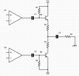
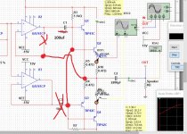
I graduated from a technical school so I know a little about designing an amp and how the several classes work, but i have a big doubt: I designed a circuit like this and I'm pretty sure that it isnt operating in class-b. Let me explain: I first started designing a Single-end amp (that operate in class-a) then in order to increase the efficency I added a second transistor which changed the output stage in a push-pull one. The highly biased transistor makes "cross-over distortion" appear (and consequently switch to class-b) only when you quadruplicate the value of R1 and R2. So by now (with this value) i'm pretty sure that the output stage operate in class A or AB but i don't know how tell if it is still in A and when it switch to AB.
[R3 and R4<1 Ohm, R5 is the speaker and the Op amp are buffer linked to the Volt amplification stage]
[Note that the arrow in Q2 is reversed by mistake]
In the last month I've learned a lot about power amplifiers by reading books like "High-Power Audio Amplifer Construction Manual" by Slone, and many others by Douglas Self etc..
I graduated from a technical school so I know a little about designing an amp and how the several classes work, but i have a big doubt: I designed a circuit like this and I'm pretty sure that it isnt operating in class-b. Let me explain: I first started designing a Single-end amp (that operate in class-a) then in order to increase the efficency I added a second transistor which changed the output stage in a push-pull one. The highly biased transistor makes "cross-over distortion" appear (and consequently switch to class-b) only when you quadruplicate the value of R1 and R2. So by now (with this value) i'm pretty sure that the output stage operate in class A or AB but i don't know how tell if it is still in A and when it switch to AB.
[R3 and R4<1 Ohm, R5 is the speaker and the Op amp are buffer linked to the Volt amplification stage]
[Note that the arrow in Q2 is reversed by mistake]
Attachments
Last edited:
Try altering your circuit like this.
1/ Link the base of the output transistors.
2/ Do not connect the lower opamp output.
3/ Move the feedback point of the top opamp to the output node.
4/ Change the 10uF to something larger as shown.
5/ Increasing R3 and R7 (keep them equal) will make it an easier load for the opamp. Try 2k2 or 3k3.
Doing this will give you an idea of what class B operation looks like and from here it can be altered to class AB.
Attachments
I think there's been some misunderstanding, excuse. I know that it isn't a good schematic, i try to understand the role of every single component before adding a new one. My question was: "how do i realize if the amp is class A instead of AB?"
I can take hundreds schematics better than this but i want to understand the project choices that lead the designer.
I took a look at this Push-Pull vs. Single-Ended in Class A Operation and realize that i have to watch the current (across the emitter resistor) instead of voltage cause there is no difference between the classes if i analize only the voltage with the scope.
Thank you all.
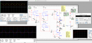
Your output stage most closely resembles a push pull type (but with very ill defined operating points for the output transistors, particularly in a real build with real parts).
During the time the transistor current swings from the bias current value up to but not exceeding twice that level of bias current then the stage is in class A. Once that limit is exceeded then the stage has slipped into AB operation.
Your circuit will have problems in translating from simulation to a real build due to wide transistor parameter variation.
This depends on the power supply voltage, the idle current through R3 and R4 and the load resistance. For a nice easy to understand amp circuite you might look at Nelson's A40 article. It's a simple circuite but takes some big hardware that is a big transformer and BIG heatsinks.
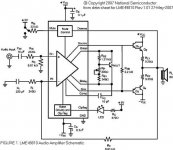
You might try from a starting point similar to your topology, but known to work well. I have built this and it works very well. In stock form as designed, it runs a very low bias current of maybe 3mA. I changed R7 and R8 from 10R to 0.5R and the bias went up to 35mA, at which point I think for most listening at normal volume levels with headphones, is Class A. When driven to higher output levels above 35mA, it goes out of Class A.
Headphone Amplifier
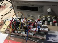
Here is my build:
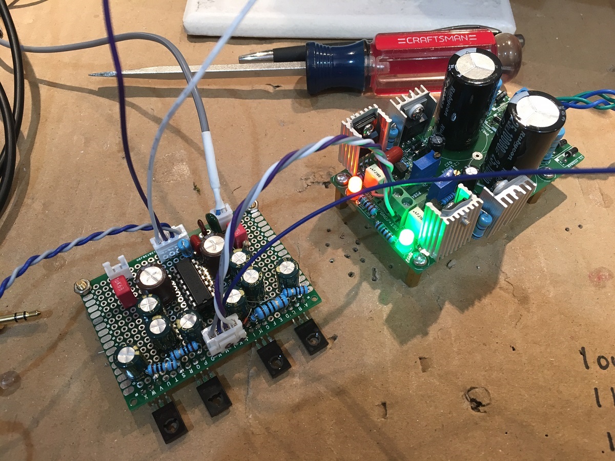
But, I think this topology may be close to what you are looking for: an opamp driving a push pull complenmentary output stage. The oapmp keeps the dc offset under control and it never goes beyond 1mV or so.
Headphone Amplifier
An externally hosted image should be here but it was not working when we last tested it.
Here is my build:
But, I think this topology may be close to what you are looking for: an opamp driving a push pull complenmentary output stage. The oapmp keeps the dc offset under control and it never goes beyond 1mV or so.
You might try from a starting point similar to your topology, but known to work well. I have built this and it works very well. In stock form as designed, it runs a very low bias current of maybe 3mA. I changed R7 and R8 from 10R to 0.5R and the bias went up to 35mA, at which point I think for most listening at normal volume levels with headphones, is Class A. When driven to higher output levels above 35mA, it goes out of Class A.
Headphone Amplifier
An externally hosted image should be here but it was not working when we last tested it.
Here is my build:
But, I think this topology may be close to what you are looking for: an opamp driving a push pull complenmentary output stage. The oapmp keeps the dc offset under control and it never goes beyond 1mV or so.
Thanks i really appreciate it!
Do you think that this kind of approach can go well for higher power?
I see no heatsink on the BDs, are they still cool?
Do you have the schematics of the power supply on the right?
You build looks nice and clean, mine is a tangle of wires...
Attachments
Wrong...and the bias went up to 35mA, at which point I think for most listening at normal volume levels with headphones, is Class A. When driven to higher output levels above 35mA, it goes out of Class A.
Squeezing one rail side to zero - at that moment the output current measures 70 mA (see Kirchhoff’s circuit laws) and your amp goes to Class B. It is the double value of bias current that makes amp leaving Class A. Mooly also clearly stated this in post #10.
Thanks i really appreciate it!
Do you think that this kind of approach can go well for higher power?
I see no heatsink on the BDs, are they still cool?
Do you have the schematics of the power supply on the right?
You build looks nice and clean, mine is a tangle of wires...
The PSU is the Nazar shunt regulator circuit. Prasi made those so you will have to contact him to see where the schematic is. I have operated it with a simple linear 7815/7915 regulators following a CRC from a trafo. Even that works well enough without audible noise.
When biased at stock (default) value of 3mA no heatsink needed. But at 35mA. Definitely needs a moderate heatsink as its about 4.2w dissipation.
To get higher power requires bigger PSU rail voltages. You either need to get special HV opamps (which I recently found out from Mooly that LT makes 150v p-p opamps. ). Then use transistors with higher current capability, bigger heatsinks, etc. but I think the basic opamp might be able to drive a bigger transistor just fine if you pick the right one capable of higher currents. You can also bootstrap a common +/-15v opamp to get higher swing. But again, need to check to see if opamp can drive enough current.
Last edited:
Do you think that this kind of approach can go well for higher power?
Wrong approach.
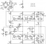
I’ve kindly posted you two schematics on which you should study hard and make amplifiers out of them. On the way you’ll learn a lot and maybe someday become apprentice of amp designer.
Your posts in this thread so far have shown anything but kindness. Maybe someday you will become apprentice of person with good manners?Lazy Cat said:I’ve kindly posted you two schematics on which you should study hard and make amplifiers out of them. On the way you’ll learn a lot and maybe someday become apprentice of amp designer.
Your posts in this thread so far have shown anything but kindness. Maybe someday you will become apprentice of person with good manners?
Not likely. Shouldn't be tempted to post anything anymore, makes no sense.
Wrong approach.
I’ve kindly posted you two schematics on which you should study hard and make amplifiers out of them. On the way you’ll learn a lot and maybe someday become apprentice of amp designer.
Okay, wrong approach but you did not explain why...You post a sch from a datasheet and a sch with three mistakes, again i know that it isn't a good sch (mine) because there is no CCS, no negative-feedback etc. Is a push-pull stage without anything else and i did it only to figure out when class A switch to AB.
I wanted to find a good method, a sort of "algorithm" that (by measurements with a scope or something like) tells you when the OPS switch to AB, nothing more nothing less.
Last edited:
- Status
- This old topic is closed. If you want to reopen this topic, contact a moderator using the "Report Post" button.
- Home
- Amplifiers
- Solid State
- How to tell if this amp is in class A or AB ???