Look at each side's current at high signal.
If it is Sine, it is A.
If it is half-Sine, it is B.
If even part of it is cut off, it is AB.
If it is Sine, it is A.
If it is half-Sine, it is B.
If even part of it is cut off, it is AB.
Is this a simulation or a build?
In simulation, *identical* transistors biased the same way will conduct exactly the same current.
In a real build with +/-5% resistors and +/-50% transistors, you can have more than 2:1 difference between "identical" transistors. In this circuit this will give a large DC at the output. Such questions are key to design.
Is this a simulation or a build?
In simulation, *identical* transistors biased the same way will conduct exactly the same current.
In a real build with +/-5% resistors and +/-50% transistors, you can have more than 2:1 difference between "identical" transistors. In this circuit this will give a large DC at the output. Such questions are key to design.
Thanks for the hints
What i do (almost) every day is reading->simulate->place component on breadboard->WTF??->back to read, so i'm learning i think (hope) to build next year maybe.
A push-pull output stage uses some bias.
The +ve side passes bias current towards the output.
The -ve side passes bias current from the output.
When there is no output, then the +vecurrent = -vecurrent.
When the output passes some current you will find that Output current = +vecurrent+ -vecurrent
Take this example:
The bias current = +100mA.
When the +vecurrent has increased to +160mA and the -vecurrent has decreased to -40mA, then you will find that the output current is +160mA + (-40mA) = +120mA
You will find that the 8r0 load sees a voltage = +160mA*8r0 = +1.28Vdc
Keep increasing the drive to bring the +vecurrent to +199mA and the -vecurrent to -1mA, then the load voltage will be (+199-1)*8r0 = +1.584Vdc
This set of output conditions has used BOTH upper and lower output devices to control the output current and voltage. This is ClassA. BOTH upper and lower control the current.
Now increase the +ve current to +200mA and you will find that the -ve current is just a tiny bit more -0mA. The -ve side is no longer controlling the output current. Small changes in drive do not create proportionate changes in the -ve current. This is ClassB.
One side is controlling the output and one side is either OFF, or so close to OFF that there is no effective control.
Let's jump to +300mA and -0mA for the upper and lower currents. The output is +300-0 = +300mA.
The load voltage is +2.4Vdc
In the above we usually approximate and say that when the output current reaches twice the bias current of the push-pull output stage that the circuit transitions from ClassA to ClassB. We refer to the amplifier as ClassAB
The above description of operation can be applied to a discrete power amplifier, or to an integrated chipamp, or to an opamp. Any amp that uses a dual polarity power supply and a push-pull output stage follows that same operation for the transition from ClassA to ClassB.
Last edited:
Yes, push-pull on a dual polarity supply work the same way.What about quasi complimentary output stages, same analysis applies?
Push the drive voltage up, or down. a little from zero and the upper current varies in the opposite direction to the lower current. It's the difference between upper and lower currents that equals the output current.
First of all, I'm sorry for my poor english.
In the last month I've learned a lot about power amplifiers by reading books like "High-Power Audio Amplifer Construction Manual" by Slone, and many others by Douglas Self etc..
I graduated from a technical school so I know a little about designing an amp and how the several classes work, but i have a big doubt: I designed a circuit like this and I'm pretty sure that it isnt operating in class-b. Let me explain: I first started designing a Single-end amp (that operate in class-a) then in order to increase the efficency I added a second transistor which changed the output stage in a push-pull one. The highly biased transistor makes "cross-over distortion" appear (and consequently switch to class-b) only when you quadruplicate the value of R1 and R2. So by now (with this value) i'm pretty sure that the output stage operate in class A or AB but i don't know how tell if it is still in A and when it switch to AB. 😕
[R3 and R4<1 Ohm, R5 is the speaker and the Op amp are buffer linked to the Volt amplification stage]
[Note that the arrow in Q2 is reversed by mistake]
With due respect, you still need to read a lot more, and start with the basics, then climb the ladder step by step.
Guessing by the knowledge you displayed so far, you are at the stage of designing single transistor gain stages.
Fine, fully learn that, then progress to the next stage, and so on.
You are still too far from the Power Amp stage.
Which you will reach someday, just go step by step, don´t take shortcuts because there isn´t any.
Did i ever said that i'm the master of amplifier design? I'm here to learn, i'm not trying to sell a product or to teach someone...Did you read post number 20? Cause i clearly said that i run the simulation to understand when the A class switch to AB in a pushpull stage.
I kept doing the same mistake: watching the voltage instead of current so this is the reason why i've posted. I use opamp just to save time. Hope in the future there will be more constructive comments, like AndrewT and many others has done.piz1 said:Is a push-pull stage without anything else and i did it only to figure out when class A switch to AB.
Regards.
a simulator answers questions.Did i ever said that i'm the master of amplifier design? I'm here to learn, i'm not trying to sell a product or to teach someone...Did you read post number 20? Cause i clearly said that i run the simulation to understand when the A class switch to AB in a pushpull stage.
I kept doing the same mistake: watching the voltage instead of current so this is the reason why i've posted. I use opamp just to save time. Hope in the future there will be more constructive comments, like AndrewT and many others has done.
Regards.
You need to know how to formulate those questions to get useful answers.
A simulator is not a teaching tool. It is an analytical tool for one who already knows how the circuit operates.
Ask a simulator a stupid question and it will give you an equally stupid answer.
Hi, I hope you might find this useful, from approx 40mins onwards Nelson talks about class A and AB YouTube
Thanks, it's really interesting i will watch even the part 2 🙂
I totally agree.A simulator is not a teaching tool. It is an analytical tool for one who already knows how the circuit operates.
Given that I don't have a current probe but only standard probes that came with my Rigol scope:
I wanted to see the cutted wave.
In a single-end configuration it's easy to see because the only thing you need to do is to connect the probe of your oscilloscope to the emitter (or collector) and play with the biasing. That's becuse voltage and current have the same waveform.
Probably i'm missing something but in a Push-Pull stage it's different and the easiest way that comes to mind is with a current probe (that i don't have).
Regards.
Last edited:
When i wrote this
I mean I was expecting to see this thing happen.
That's all.
Regards.
I was referring to thisI wanted to see the cutted wave.
I mean I was expecting to see this thing happen.
That's all.
Regards.
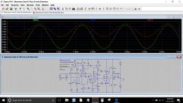
This is the classic 'blameless' amplifier set up with 1 Amp bias current flowing.
The first image shows an applied input voltage that develops a load current (in the 8 ohm load R22) of -/+ 2 amps. You can also see the currents in the two emitter resistors R20 and R21. These are still a sine wave and have an amplitude varying from 0 to 2 amps.
(Remember we said the amp would be in class A up to twice the bias current setting)
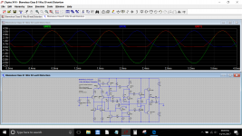
Now we change the load to 4 ohms which means twice the current will flow in the load. Notice now how each transistor now gets cut off as its current approaches zero, and consequently how the currents become a distorted waveform. The load current is still 'pure' but the amp has slipped into class AB as the bias current is now not sufficient to support class A operation into this impedance and at these levels.
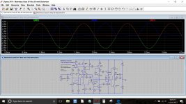
In the final image the bias current is zero, pure class B. There is no 'overlap' in conduction of the output transistors, each supplies and conducts for just 180 degrees of the cycle. The distortion is still surprisingly low at around just 0.02% THD.
The first image shows an applied input voltage that develops a load current (in the 8 ohm load R22) of -/+ 2 amps. You can also see the currents in the two emitter resistors R20 and R21. These are still a sine wave and have an amplitude varying from 0 to 2 amps.
(Remember we said the amp would be in class A up to twice the bias current setting)
Now we change the load to 4 ohms which means twice the current will flow in the load. Notice now how each transistor now gets cut off as its current approaches zero, and consequently how the currents become a distorted waveform. The load current is still 'pure' but the amp has slipped into class AB as the bias current is now not sufficient to support class A operation into this impedance and at these levels.
In the final image the bias current is zero, pure class B. There is no 'overlap' in conduction of the output transistors, each supplies and conducts for just 180 degrees of the cycle. The distortion is still surprisingly low at around just 0.02% THD.
Attachments
- Status
- Not open for further replies.
- Home
- Amplifiers
- Solid State
- How to tell if this amp is in class A or AB ???