This circuit was published in Wireless World issue of July 1970, following an article the previous month entitled "Class Distinction in Audio Amplifiers".
The first mentioned article is available at http://www.keith-snook.info/wireles...orld-1970/15-20W Class AB Audio Amplifier.pdf
Linsley-Hood did listening comparisons with his 1969 Class A amplifier and commented that his test panel could not distinguish between the two.
The Class AB amplifier runs at a fraction of the Class A amplifier current demand, and can be built using simple methods such as matrix board or "dead bug" style - as a project it should be a grade 101.
There was considerable debate about this amplifier in Wireless World about the recommended standing current of 200 m.A. - more in line with "First Watt" philosophy that now has some following.
I have looked at modelling this AB design and the 1996 Class A version using LT Spice - models by Cordell.
These can be altered to see how distortion and harmonics are affected by changing the standing current
I will post the simulations by PM or the thread subject to whatever interest there may be.
I have also simulated a split supply rail version with a few changes - the results are an improvement.
These can be altered to see how distortion and harmonics are affected by changing the standing current
Very good insight to subject can be found at page 11:
Dropbox - Barney Oliver distortion in B-class.pdf
")
This circuit was published in Wireless World issue of July 1970, following an article the previous month entitled "Class Distinction in Audio Amplifiers".
The first mentioned article is available at http://www.keith-snook.info/wireles...orld-1970/15-20W Class AB Audio Amplifier.pdf
Linsley-Hood did listening comparisons with his 1969 Class A amplifier and commented that his test panel could not distinguish between the two.
The Class AB amplifier runs at a fraction of the Class A amplifier current demand, and can be built using simple methods such as matrix board or "dead bug" style - as a project it should be a grade 101.
There was considerable debate about this amplifier in Wireless World about the recommended standing current of 200 m.A. - more in line with "First Watt" philosophy that now has some following.
I have looked at modelling this AB design and the 1996 Class A version using LT Spice - models by Cordell.
These can be altered to see how distortion and harmonics are affected by changing the standing current
I will post the simulations by PM or the thread subject to whatever interest there may be.
I have also simulated a split supply rail version with a few changes - the results are an improvement.
So - what's the point?
BTW - a lot of material, published by JLH, here:
John Linsley Hood
It is a grade 101 offering that someone like myself with little understanding of electronics 41 years ago, newly married with a wife, child and mortgage could build. In my case buying the parts over an extended period for what out-of- pocket spare cash I could afford these for the 1969 Simple Class A circuit.
I also built the direct coupled 1996 version when it appeared as none of the more fashionable circuits I build in the intervening years gave me the same level of satisfaction.
The same can be said of any commercial amplifiers I have ever owned.
Class A amplifiers are inefficient and generate a lot of heat, are more bulky than normal, and they need space to breathe, OK for a person living alone. However there are domestic harmony questions of siting such equipment where it will be out of reach of children without being a dominant feature of the family lounge.
The point of my simulations is to see if the Class AB amplifier stands to give the same level of satisfaction as the Class A amplifier as inferred by Linsley-Hood with greater efficiency, less bulk and less expense.
Last edited:
Its always interesting to see how these old designs perform (simulate)
The link takes me to the home page (its a forum issue redirecting and its done this before with Keith Snook pages) so try pasting just the second part of the link here into your browser and it should take you straight to the pdf. If that doesn't work then add the first bit as well
Nymeria.
keith-snook.info/wireless-world-magazine/Wireless-World-1970/15-20W%20Class%20AB%20Audio%20Amplifier.pdf
Very good insight to subject can be found at page 11:
Dropbox - Barney Oliver distortion in B-class.pdf
The feedback from Letters to the editor predated this paper of which I have been aware. You can read this in the link provided by your compatriot to compare the two counter arguments to Linsley-Hood's approach.
I know that in a high power amplifier the need to parallel output devices offers an opportunity to comply with such arguments with each set of devices contributing to an overall current that increases the Class A operating power level. There is still a need to set the standing current correctly and maintain this under operating conditions involving changes of temperature.
This sort of project is more advanced than the one proposed here. Devising a suitable layout and trouble-shooting of a more complex amplifier would be more difficult and there would be more chances of making errors.
Unless one has the backing at hand of someone having experience in building electronic projects the outcome may be a total deterrent to further involvement.
Its always interesting to see how these old designs perform (simulate)
Thanks for that. I am still finding my way with simulations it will be good to have some oversight from other contributors.
Member
Joined 2009
Paid Member
JLH 1996 Class A
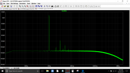
Originally I simulated this with the transistors that Linsley-Hood employed using manufacturers .models. I have since changed the transistor complement to fit the .models by Cordell whose tutorials I followed for THD testing at 1kHz and 20kHz. I still have 2N3055's in my amplifier.
I have left the electrolytic capacitor values at or close to the values used by JLH and taken the liberty of changing the input capacitor value to 10uF.
In this I departed from the dc simulations in Cordell's tutorial and made no attempt to get close to dc response by increasing the values to the extremes necessary.
I found it easy to fit the two simulations in the one file by leaving the relevant commands on screen with those de-selected by changing the status to comment. The distortion figures I noted in comment blue are those not in brackets in the SPICE error log.
Distortion results are one thing however the relationship between the harmonics is what interests me in the FFT results.
The input signal levels are to match those I used in the JLH1970 original AB circuit and my simulation of a modified version with some changed/added circuit elements.
I will post the other simulations after seeing what comments are made either on the results or validity of my test method.
Attachments
No feedback comment yet, but some views, so hopefully I have not strayed too far off the beaten track - I did this on my hour's bush-walk this afternoon and having travelled half way down from the top of the hill to find my perceived short cut came to a dead end I had to scale back up to the top again to find my way back home.
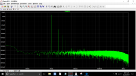
Anyway I am posting the simulations for the original JLH Class AB with some more modern transistors in the complement. I doubled the value of some electrolytic caps in these simulations. In some FFT results the magnitude of the third harmonic dominates with the level of standing current recommended by Linsley-Hood.
This posed the question of is this as good as it gets or is there a sweet spot with some other level of output stage standing current. There are one or two things that could be changed in this circuit towards that end. I'll save these for my next post.
Attachments

Interesting. The JLH1970 looks to good but the 3rd harmonic does dominate as you would expect. The JLH69 is pretty much as expected with relative high distortion by modern standards (but we all know how good it sounds). The JLH69 was from my own sim and running 1.2 amp bias with a 27 volt rail.
but the 3rd harmonic does dominate as you would expect. The JLH69 is pretty much as expected with relative high distortion by modern standards (but we all know how good it sounds). The JLH69 was from my own sim and running 1.2 amp bias with a 27 volt rail.Attachments
I am curious about THD 20kHz over every signal level at a known bias.
Please plot thd versus output power at a given quiescent current.
Several plots ( at various bias ) would be great to look for a "best" bias.
It depends if the requirement for the lowest THD or the best disposition of the harmonics.
This is a simple amplifier - one has to accept there is less negative feedback reduce the levels of the harmonics so attention to structure is important if the aim is to emulate that of the Simple Class A amplifier.
2017 Revamp
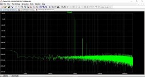
I changed the original circuit to run from split supplies of +/- 24 volts in a similar way to the 1996 Class A amplifier and substituted a Constant Current Source for Q3 Bootstrap Collector load.
Simulations indicated the 47R resistor collector load for Q4 was not necessary.
In the first instance the CCS current was roughly 6 m.A. but more is better so I gave that a boost.
I tried various biasing methods for the output stage - wire wound pots are a bit expensive so I tried resistors, diode resistor combinations which would be cheaper but less flexible.
This led me to consider using a Vbe multiplier which resulted in an unexpected improvement over all other bias arrangements. In this the second harmonic dominates in the FFT plots.
According to Linsley-Hood in 1996 contemporary thinking was all harmonics should be less than 0.02% although 2nd harmonic is probably undetectable below 0.05% so I feel satisfied with what I see from these simulations - indicative only as these may be.
The transistor complement apart from the output devices is humble and these should be readily available off the shelf from retail electronics stores. I have tested at other models in Cordell's library and these are my choice.
R4 and R15 will need to be made up from a combination of a resistor and trimpot.
There is a little more complexity with this circuit than the original which should still be good and safe enough for first time builders. An output capacitor obviates the need for a dc protection circuit which will increase the costs.
There is some room to modify the original JLH circuit to include the Vbe multiplier circuit for a better result and to change some resistor values in the bootstrap collector load of the Vas - albeit that the inclusion of the 47R collector load resistor of the driver transistor in series with the bootstrap is a complicating factor.
The current drawn by the bootstrap/Vas is low (2-3 m.A.). While adequate to drive the high gain MJ481/MJ491pair the MJL pair has a lower current gain so the best is not being made of their capabilities - I had expected a better result in my simulations.
Others may wish to explore this - my inclination would be to recast my direct coupled circuit for single supply use.
Attachments
Hmmm
Just tried like for like to compare with the other FFT above.
Oops! I don't know how but somehow the 8R load went missing in this simulation. That changes the picture of the FFT which is not quite so rosy - my face is red.
There is no real difference now if the output standing current bias is set by a vbe transistor or a resistor.
Attachments
- Status
- This old topic is closed. If you want to reopen this topic, contact a moderator using the "Report Post" button.
- Home
- Amplifiers
- Solid State
- Simple Class AB - Linsley-Hood 1970