My point is that transistors are voltage driven components.
Agreed.
In what you call CFA, the inverting input is driven by a fraction of output voltage.
If so, it is driven in a very poor manner. Consider what happens with low open loop gains. The inverting input will ignore what the voltage divider is trying to do to it. The inverting input voltage is always much better described as following the non-inverting input voltage and being driven by the difference between the ground and output stage currents.
The only difference with VFA is that the inverting input low impedance is part of the feedback network.
That is not the only difference. CFAs exhibit constant bandwidth over a range of closed loop gains in which VFAs have a constant gain-bandwidth product. There are other differences too.
As forr said, the first stage of a closed loop amplifier make the difference between input voltage and something that come from the output.
As far I know you cannot make the difference between a voltage and a current.
If you really believe this, you need to see post 812. Forr hasn't replied to it.
On another note, I have a great deal of respect for anyone who can converse in more that one language. I have only a smattering of French.
Well, I put that up for a couple of pictures in it that relates to my question as to what happens when you apply a Cf across the Rf in a CFB and in a VFB amp.
On a VFB amp, it would roll off the frequency response. It does just the opposite in a CFB amp. Peaking and ringing and osc.
I thought that might help some to rethink their arguments on how CFB work.
THx-RNMarsh
I think things might go better if we all paid more attention to your tagline.
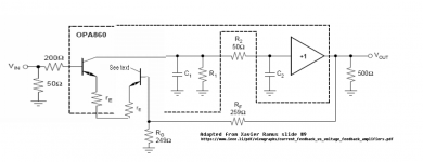
forr, maybe I would better understand your views if you could explain why I should apply your voltage/transconductance paradigm to the attached circuit. Also, I'd appreciate it if you could advise me how you embed an image in text rather than attaching it. I see the tag but don't know how to upload the image. Your help would be appreciated.[/QUOTE]
Upload your image file with the attachments manager.
Preview your post.
In the "Attach files" section, the name of your image file appears.
With the mouse right button, copy the address of the link.
Then click on icon "Insert image" and paste the address of the link.
Your image id displayed.
You can do that with all images on the forum.
I strongly advice anybody wanting to upload images to first reduce their size using free program [url=http://faststone.org/FSResizerDetail.htm]FastStone Photo Resizer - Powerful Image Converter/Resizer[/url]
640 or 800 pixels width is most of the time perfectly adequate for a nice viewing.
Not free (<20 $) but fantastically useful is this screen capture program, I am using it everyday :
[url=http://faststone.org/FSCaptureDetail.htm]FastStone Screen Capture - The Best Screen Capture Software[/url]
For diagrams, saving them in PNG format, option 256 colors, is very economical in bytes.
Upload your image file with the attachments manager.
Thank you, Forr! I'll give it a try.
I have been thinking about that for a long while. If the incoming current is delivered from an insufficient impedance (then looking as a voltage source in series with a modest resistor or, of course, the equivalent, a current source in parallel with a modest resistor), the transistor does not operate as a common base.Of course. Take the example of a common-base stage. The input is a current into the emitter. That current changes the Vbe value. But the input is a current, nevertheless. Interestingly, seen from the inv input of a CFA, you are looking at a common base stage
I simulated an evolution of my previous circuits with a single input transistor.
I added an ideal buffer at the output so that Rg is fed by a null impedance. The amplifier circuit has a voltage gain of 20 dB set by the feedback network, 9/1 kOhm or 900/100 Ohm.
Measuring the T1 emitter currents in open and closed loop, I found that in closed loop the impedances seen by the emitter of this transistor are 36 and 28 kOhm respectively.
Attachments

Last edited:
Maybe the attached circuit can show this...My point is that transistors are voltage driven components.
In what you call CFA, the inverting input is driven by a fraction of output voltage. The only difference with VFA is that the inverting input low impedance is part of the feedback network.
As forr said, the first stage of a closed loop amplifier make the difference between input voltage and something that come from the output.
As far I know you cannot make the difference between a voltage and a current.
I have added a second input buffer to the Ramus slide 9. This makes it a "modern VFA" as in slide 12. Without the 2nd input buffer it is a CFA slide 9.
The difference is the base current that flows in the 2nd buffer when it is used. When the 2nd buffer is used the beta of the 2nd stage reduces the feedback current to the input stage.
This shows the type of feedback does not change only the relative amount of current fed back. So both forms do use voltage feedback. Relative current levels cannot change the fundamental operation principle.
The main difference is the relative current level at the inverting input changes, so the voltage divider resistor values for the CFA need to be lower for high open loop gain and for the HF end.
If anyone is interested in analysis of a CFA as a CFP a PDF is here. It uses the SPICE BJT model where Ic is generated by base-emitter voltage. So any attempt to drive a transistor base or emitter with a current source the circuit must first create a base-emitter voltage to allow that current to pass through. That's obvious when you see the collector-emitter current in the SPICE model is modeled as a current source which means you can't force current through the collector or emitter externally (assuming you work below it's breakdown voltage) unless you change the base-emitter voltage first.
I am progressively updating my website here PAK Project – Course Outline - PAK2 devo. It will take a while.
Cheers
Attachments
That's exactly what I wrote more than once...The inverting input voltage is always much better described as following the non-inverting input voltage
...and that's exactly what I contest. The emitter imposes the voltage by delivering the necessary current at the varying impedance it sees at the feedback node. It is not the feedback which imposes its current in the emitter. This is so because the current feedback in Rf signal can't get ahead of the signal voltage at T1 emitter. If it does not happen like that there is a space-time violation. T1 base-emitter voltage commands, Rf current obeys.and being driven by the difference between the ground and output stage currents.
That's exactly what I wrote more than once...
...and that's exactly what I contest. The emitter imposes the voltage by delivering the necessary current at the varying impedance it sees at the feedback node. It is not the feedback which imposes its current in the emitter. This is so because the current feedback in Rf signal can't get ahead of the signal voltage at T1 emitter. If it does not happen like that there is a space-time violation. T1 base-emitter voltage commands, Rf current obeys.
The same "space time" limitation that you argue prevents current feedback in the CFA must prevent voltage feedback in the VFA.
Perhaps the problem is with the word "driven". How about "is subjected to"? The inverting input of a VFA "is subjected to" a portion of the output voltage. That of the CFA "is subjected to"? "accepts"? the difference between the ground and output stages currents. If it does not, then Kirchoff is violated.
This is so because the current feedback in Rf signal can't get ahead of the signal voltage at T1 emitter. If it does not happen like that there is a space-time violation. T1 base-emitter voltage commands, Rf current obeys.
This is nonsense. The translinear relationship between Vbe and Ic is satisfied in the steady state for all of these circuits. The cause/effect arguments are pointless.
This is nonsense. The translinear relationship between Vbe and Ic is satisfied in the steady state for all of these circuits. The cause/effect arguments are pointless.
🙂 😎
-RNM
If the incoming current is delivered from an insufficient impedance (then looking as a voltage source in series with a modest resistor or, of course, the equivalent, a current source in parallel with a modest resistor), the transistor does not operate as a common base.
Forr, this is nonsense. A bjt common base circuit configuration is defined as a circuit where the reference (or ground, if you wish) is connected to the base, and the input is connected to the emitter, collector being the output of course.
It has nothing to do with levels of signals or impedances in the circuit.
Jan
We have two inputs. The current entering emitter is not from a pure current source.There are very good reasons for which current coming from the output through Rf, which also change the voltage across Rg, to be seen as a change of load impedance by T1 emitter. Disconnecting Rf, you've got an emitter degenerated transistor. It's would a bit strange than reconnecting it would change this status to common base.Forr, this is nonsense. A bjt common base circuit configuration is defined as a circuit where the reference (or ground, if you wish) is connected to the base, and the input is connected to the emitter, collector being the output of course.
It has to do with Ohm's law.It has nothing to do with levels of signals or impedances in the circuit.
Last edited:
And not in dynamic state ? Not the slightest time and phase delays between the output voltage and the inv input ? Perfect response to square waves, then.Originally Posted by forr
This is so because the current feedback in Rf signal can't get ahead of the signal voltage at T1 emitter. If it does not happen like that there is a space-time violation. T1 base-emitter voltage commands, Rf current obeys.
This is nonsense. The translinear relationship between Vbe and Ic is satisfied in the steady state for all of these circuits.
We have two inputs. The current entering emitter is not from a pure current source.There very good reasons for which current coming from the output through Rf, which also change the voltage acroos Rg, to be seen as a change of load impedance by T1 emitter. Disconnecting Rf, you've got an emitter degenerated transistor. It's would a bit strange than reconnecting it would change this status.
It has to do with Ohm's law.
As usual, you quote something, then dodge it and start talking about something else. A good tactic to score debating points, but lousy to progress understanding. But we all have our priorities here I guess.
You said that at some impedance levels a common base does not work as common base. That is utter nonsense, because the topology is defined as common base. You can try to mislead us and tap-dance all you want, but you were plain wrong, and you know that.
Most of us here do admit that we are wrong if we are. Unlike debating points, it does earn respect.
Jan
Common base does not have current gain, the input current (from feedback network) is translated 1:1 (almost) to the VAS stage.
In a VFA this is not possible, no matter how high the (potential) current delivery at the inverting node is.
Nothing to do with ohms law, but with semiconductor theory.
In a VFA this is not possible, no matter how high the (potential) current delivery at the inverting node is.
Nothing to do with ohms law, but with semiconductor theory.
It has been said many times : VFA input stage is only a CFA input with a buffer.The same "space time" limitation that you argue prevents current feedback in the CFA must prevent voltage feedback in the VFA.
The input voltage and then base voltage of T1 drive the whole. Is T1 "driven" by the feedback current or by the dynamic impedance seen by its emitter ?Perhaps the problem is with the word "driven".
And a motorbike is only a bicycle with an added engine...hence we should call all two-wheelers bicycles.It has been said many times : VFA input stage is only a CFA input with a buffer.
[....]
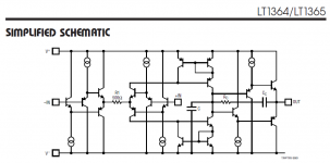
Apart that, your statement is only true for a circuit like LT1364, but not for most other VFA topologies.
A standard diff input is not a buffer, as it cannot supply or sink more current to the other leg (and into the VAS) than the tail current. The emitters are isolated by the B-E junction.
In a CFA, the current conveyed into VAS is not dependent on the biasing of the neg. input transistors.
This alone justifies a different naming convention....
A transistor with an emitter degenerated by a resistor of moderate value and connected to ground does not really operate as a pure common base. In that case, the current coming from a pure current source is modified by the emitter voltage (refered to ground).You said that at some impedance levels a common base does not work as common base. That is utter nonsense, because the topology is defined as common base.
Look at the second transistor of a folded cascode, it is connected to the collector of the first transistor (a current source) and either to a CCS or to a resistor. To the CCS, a change of bias of the common base transistor does not alter the output current. It does with the resistor and that is a similar situation in which the CFA input stage transistor is. The entering current in its emitter comes from a too low impedance to consider T1 as operating in true common base and then the CFA to merit the term of current feedback.
I am far from being alone. I am sceptic about the CFA concept (not the topology) since long before the birth of AudioDiy. And here I posted some messages about it in 2005 I think. Having published some Peter Baxandall's texts, you may know what he thought about CFA. Nobody said he was wrong at the time.You can try to mislead us and tap-dance all you want, but you were plain wrong,
Who decides who is right and who is wrong ? I generally try to avoid saying people are wrong as it sometimes has unpleasant consequences. I prefer to discuss the arguments and the points of view.Most of us here do admit that we are wrong if we are.
- Home
- Amplifiers
- Solid State
- Current Feedback Amplifiers, not only a semantic problem?