Hello Guys, so the feedback pad on the original boards from Jen, would it be better to run that all the way to the binding Post or just to the pads on the Output Boards?
Secondly what about the ouput pads, connect all 6 pads at the Output boards and run one wire to the post or 1 from each board or 3 from each board?
Lastly, I misplaced the answer from Stuart regarding substitution of Q111. The answer was to use one of the MJE150XX devices. which one again?
MJE15033OS or MJE15032OS
Many Thanks, I should have it up and running this weekend.
Stereo Operation
Dual 25VAC 1KVA Toroid, Dual Ultrafast Rectifiers boards, 250,000 uF filter Capacitance, 2 x 1.8mH coils in CCLC configuration.
My line voltage is a constant 122VAC, I am very close to the Sub Station. I should get 32VDC rails, all things being equal to the Build list I should get maybe 40Watts of Class A operation?
If the heatsinks stand up, I may kcik the transformer up to 40VAC secondaries. 🙂 🙂 🙂 🙂 🙂
Regards
Anthony
Anthony,
for Japanese devices :
2SA=PNP , 2SC= NPN
European:
even numbers=PNP, uneven=NPN
American:
uneven numbers= PNP, even number= NPN.
So:
2SC3955 = NPN
BC550,BD139= NPN
MJ15024,MJE340, MJE15032= NPN
Mmmm, any one of you guys ever heard a real Krell KSA50?
[An archeologist is the perfect lover: his mate only becomes more beautifull as she grows older. For all others audio becomes more beautifull in time. The bloke who leaves audio for love is a romantic fool ]
]
for Japanese devices :
2SA=PNP , 2SC= NPN
European:
even numbers=PNP, uneven=NPN
American:
uneven numbers= PNP, even number= NPN.
So:
2SC3955 = NPN
BC550,BD139= NPN
MJ15024,MJE340, MJE15032= NPN
Mmmm, any one of you guys ever heard a real Krell KSA50?
[An archeologist is the perfect lover: his mate only becomes more beautifull as she grows older. For all others audio becomes more beautifull in time. The bloke who leaves audio for love is a romantic fool
]Comparison of the KSA 50 with the KSA50s
Hi
It was interesting to read K-amps posting re the difference between the amps.
I have a KSA100 (still being used after 20 years!) and KSA200s. Based on my positive experience with the KSA100 I unhesitatingly bought the KSA200s with the expectation that it would sound better. Well that is not always true and I am now very intrigued to see how the new Krell Clone is going to sound ?
My experience has been that the KSA100 is more dynamic that the KSA200s. Everyone seems to suggest that the later Krell's have a smoother midrange. My experience was that is possibly was not as transparent as the later models. I recently had the caps on the KSA100 pcb replaced with Black Gates and a new (Van den Hull) input cable and in my opinion it now exceeds my KSA200s. I adore the absolute control the KSA100 amp has over my speakers. The other benefit of the KSA100 over the KSA200s is that the design is so simple that you can fix it yourself. The KSA200s is a much more complex design.
The one thing that was insightfull with the KSA200s with its power indicators was that even at low volume you it would sometimes have peaks of 50-80 watt of power output . This possibly suggest that it is an advantage to have an amp that can deliver power when required.
Jozua
Coulomb, some of your questions were answered earlyer in this tread (but don't try to search them in the tons of postings):
outputs: 1 from each board to the binding post; this seems the most practical way.
feedback: directly to the binding post; this is the most practical way because the putputboards dont have connectionpoint's for the feedbackwire.
outputs: 1 from each board to the binding post; this seems the most practical way.
feedback: directly to the binding post; this is the most practical way because the putputboards dont have connectionpoint's for the feedbackwire.
Comparison of the KSA 50 with the KSA50s - addendum comment
Hi
Just as follow-up of my previous post.
In my opinion the KSA200s only really starts to impress when driven hard- especially on a big speaker. Play it through a small speaker and many of its attractive attributes gets lost.
Jozua
Hi
Just as follow-up of my previous post.
In my opinion the KSA200s only really starts to impress when driven hard- especially on a big speaker. Play it through a small speaker and many of its attractive attributes gets lost.
Jozua
Re: Comparison of the KSA 50 with the KSA50s - addendum comment
Usual Krell story.
I heard the Martin Logan Statement 1st series in Paris,France, when the system was doing its world tour.
Supplied by a truckload of Big Big Krell's, Krell crossovers, Krell pre's, Krell CD-player, one big Krell show.
If you desire the last watt: go Krell, like Fabio.
Jozua said:In my opinion the KSA200s only really starts to impress when driven hard- especially on a big speaker.
Usual Krell story.
I heard the Martin Logan Statement 1st series in Paris,France, when the system was doing its world tour.
Supplied by a truckload of Big Big Krell's, Krell crossovers, Krell pre's, Krell CD-player, one big Krell show.
If you desire the last watt: go Krell, like Fabio.
output wiring...
Since I've got a huge number of these TO3 critters being wired together I wanted to do it right, so I've been doing some reading on this...
Slone and Self both think it better to have collected the emitter resistors together to a single point, then run a single heavy gauge from that collection point to the binding post and feedback point for the amp.
In this way any slightly unbalanced currents are summed properly, and the feedback and output voltages are not accidentally some local maxima or minima...not sure if it makes that much difference, but it's really easy to do so...
HTH
Stuart
jacco vermeulen said:
[An archeologist is the perfect lover: his mate only becomes more beautifull as she grows older. For all others audio becomes more beautifull in time. The bloke who leaves audio for love is a romantic fool
They seem to be speaking to you Stuart!!!!
I shouldn't say it too loud though,

We are all nuts, some a little more than others. That's why I seldom speake of my hobby with others. And this is the reason I love so much these forums... I can flock with my species...😀
Or the copper bus bar again.
I was thinking of bending a bus bar on both sides around the heatsink, running next to the output boards.
Another bus bar attached to it under a 90 degree corner and bolted to the binding post on the other end.
The feedback i could tap at the symmetrical point.
Hence my question about how to silverplate bus bars.
Saves on spaghetti.
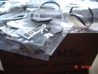
Speaking of spaghetti:
anyone have a clue what a diy dork can do with a box full of Taiwan flat belts ?
MCM sent my order to New Caledonia first, it returned, then sent it me, for me to discover the true content.
With the shipping and handling costs added these are really fancy belts, friends.
Spot the real fool !
I was thinking of bending a bus bar on both sides around the heatsink, running next to the output boards.
Another bus bar attached to it under a 90 degree corner and bolted to the binding post on the other end.
The feedback i could tap at the symmetrical point.
Hence my question about how to silverplate bus bars.
Saves on spaghetti.
Speaking of spaghetti:
anyone have a clue what a diy dork can do with a box full of Taiwan flat belts ?
MCM sent my order to New Caledonia first, it returned, then sent it me, for me to discover the true content.
With the shipping and handling costs added these are really fancy belts, friends.
Spot the real fool !
Attachments
Q111
Assuming the 2sc3955 is not an option q111 can be an mje15028/30/32.
There are schematics from Krell that show the 15032 in that position, so an exact match probably isn't critical. It is perhaps the least taxed transistor position in the amp, having pretty much constant Ic, Vce, Vbe etc. So AFAIK a 'good' driver transistor here will be more than adequate.
Under the highest bias conditions I can envisage it will have to dissipate <100mw.
AFAIK the main reason for it to be a 'power' transistor is to make mounting it on the heatsink an easier proposition, a good thermal connection is essential for the bias compensation.
Stuart
emitter resistors...
I'm about to head out to the post office to drop a batch in the mail so...
I wanted to reiterate, if there is anyone left out there from either PCB group buy that wants some of the now infamous panasonic 0r68/10w resistors for their amps, they just need to drop me a line. My email is enabled, so it isn't hard...
oh yeah, I want to see what the critters end up in, no more anonymous constructions ...send Mark or me a picture or post it here. Many have done so but there are those of you out there that are still in the closet about your constructions...
Happy building...
Stuart
I've got some pics
Here are som pics of my progress so far.
After reading all of the posts this morning, I see that I need to attach a wire from the output to the feedback pad. For some reason I thought the feedback was optional.
Anyway, here are the pics. If yuou see something that throws up a red flag, Please let me know.
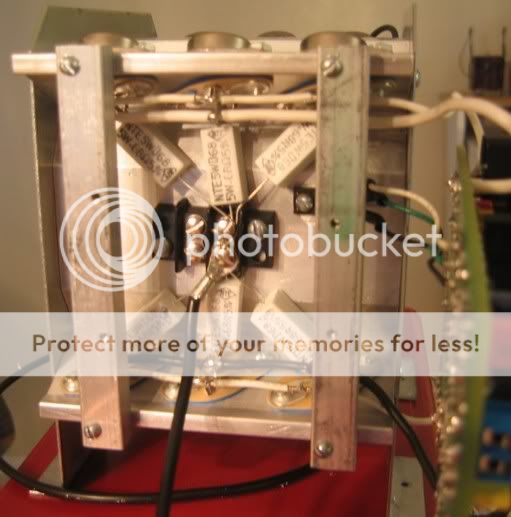
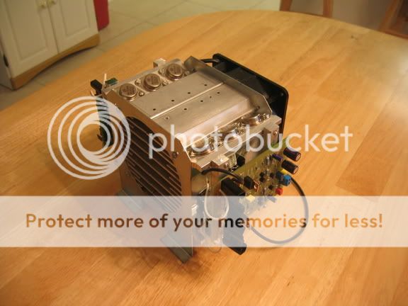
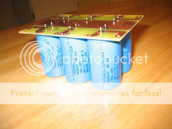
Blessings, Terry
Here are som pics of my progress so far.
After reading all of the posts this morning, I see that I need to attach a wire from the output to the feedback pad. For some reason I thought the feedback was optional.
Anyway, here are the pics. If yuou see something that throws up a red flag, Please let me know.
Blessings, Terry
Re: Q111
Thanks Stewie, I have a fantastic memory, Fantastically short that is. 🙂 🙂 🙂 🙂
Regards
Anthony
Stuart Easson said:Assuming the 2sc3955 is not an option q111 can be an mje15028/30/32.
There are schematics from Krell that show the 15032 in that position, so an exact match probably isn't critical. It is perhaps the least taxed transistor position in the amp, having pretty much constant Ic, Vce, Vbe etc. So AFAIK a 'good' driver transistor here will be more than adequate.
Under the highest bias conditions I can envisage it will have to dissipate <100mw.
AFAIK the main reason for it to be a 'power' transistor is to make mounting it on the heatsink an easier proposition, a good thermal connection is essential for the bias compensation.
Stuart
Thanks Stewie, I have a fantastic memory, Fantastically short that is. 🙂 🙂 🙂 🙂
Regards
Anthony
Terry my only comment is using a screw block to terminate the source resistors. You may introduce some noise artifiacts due to the different contact resistances. Terminating the leads with eyelet connectors, crimped and soldered would be better. Best way would just to be to solder them to a Terminal Strip at that location.
Regards
Anthony
Regards
Anthony
Yep, otherwise you wouldnt visit this forum😀 The general approach is this: Go to the nearest supermarket, buy some 5 channel stuff and be happy😀We are all nuts,
Steen😎
still4given said:If you see something that throws up a red flag, Please let me know.
Yeah: you are not supposed to build a bigger one than me !
Awesome, Terry, Thunderdome.
And what's the score with the CRCRC and the hefty 80V caps, heavy bias ?
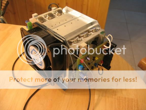
Terry,
Another thing... If I was building that kind of supply cap array for the PSU I would add a copper bus wire (maybe 16 ga) through the common plane joining all caps terminals and connections.
Have done this before and there is an advantage soundwise, specialy on bottom end.
Also... Adding a big MKP type (5/10u) to both rails (pralleling caps) will also make a big difference on smoothness. Ok, if your doing a CRCRC just do that on the last caps
steenoe said:Go to the nearest supermarket, buy some 5 channel stuff and be happy😀
No way!!!!
- Home
- Amplifiers
- Solid State
- Krell KSA 50 PCB