On July 1st 2017, my friend and I finished assembling a Dynaco QSA-300 from a kit. It sat unassembled in its original box for 41 years until last month.
We set aside the original circuit boards and substituted a homebrew circuit good for -110db distortion floor. It's a TMC amp similar to the Blameless and Honey Badger designs.
We used the factory-supplied, 41-year-old filter caps. Maybe this is nuts, but I brought them up to rated voltage slowly, trickling current in through a series 10k resistor to give them time to reform at low voltage. After a few hours, each original cap held >60V with only about 1mA of leakage. They tested fine.
We used the original chassis, transformers, rectifiers, emitter resistors, and hardware.
Everything else is new. We used new MJ21195/6 output transistors, as the factory-supplied Fairchild parts are only good to 1MHz. We used new mica TO-3 insulators, as I didn't trust the hard-anodized metal (aluminum?) insulators from the factory, some of which had scratches through the coating.
The QSA-300 can be built as a quad amp, with one pair of outputs per channel, or as a stereo amp with two pairs per channel. It can be built with either 50V or 70V rails, there are two sets of taps on the transformer secondaries. We built it as a stereo amp with 50V rails. In this configuration it's good for 75wpc at 8 ohms and 150wpc at 4 ohms. By "4 ohms" I mean it can drive 3.2 ohms in series with ANY reactive load, without exceeding the outputs safe operating area. See Cordell's chapter 15.2 regarding "overlapping elliptical load lines", that's what I'm talking about. The amp is overbuilt.
We also implemented a solid state load relay for DC offset and muting, that's on the PCB.
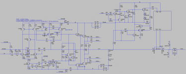
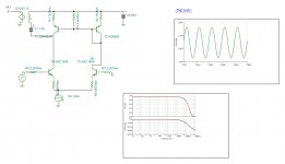
I attached two schematics. One is the "top level" showing the whole amp with power supplies and output transistors, the other is just the PCB. The "black box" in the protection circuit for the PCB is a VOM1271 optoisolator to drive the SSLR.
We set aside the original circuit boards and substituted a homebrew circuit good for -110db distortion floor. It's a TMC amp similar to the Blameless and Honey Badger designs.
We used the factory-supplied, 41-year-old filter caps. Maybe this is nuts, but I brought them up to rated voltage slowly, trickling current in through a series 10k resistor to give them time to reform at low voltage. After a few hours, each original cap held >60V with only about 1mA of leakage. They tested fine.
We used the original chassis, transformers, rectifiers, emitter resistors, and hardware.
Everything else is new. We used new MJ21195/6 output transistors, as the factory-supplied Fairchild parts are only good to 1MHz. We used new mica TO-3 insulators, as I didn't trust the hard-anodized metal (aluminum?) insulators from the factory, some of which had scratches through the coating.
The QSA-300 can be built as a quad amp, with one pair of outputs per channel, or as a stereo amp with two pairs per channel. It can be built with either 50V or 70V rails, there are two sets of taps on the transformer secondaries. We built it as a stereo amp with 50V rails. In this configuration it's good for 75wpc at 8 ohms and 150wpc at 4 ohms. By "4 ohms" I mean it can drive 3.2 ohms in series with ANY reactive load, without exceeding the outputs safe operating area. See Cordell's chapter 15.2 regarding "overlapping elliptical load lines", that's what I'm talking about. The amp is overbuilt.
We also implemented a solid state load relay for DC offset and muting, that's on the PCB.
I attached two schematics. One is the "top level" showing the whole amp with power supplies and output transistors, the other is just the PCB. The "black box" in the protection circuit for the PCB is a VOM1271 optoisolator to drive the SSLR.
Attachments
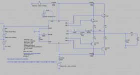
A few features distinguish this from a basic Badger:
- Triple output stage.
- LTP emitters are highly degenerated to maximize input stage linearity.
- The TMC caps are smaller than usual, which should reduce the load the TMC network places on the VAS. (Loop gain is about the same as a typical badger: shrinking the TMC caps and increasing the LTP emitter degen roughly cancel out.)
- The current mirror is set up to lift the Vce of the mirror transistors to two diode drops for Q4, and about three diode drops for Q3. This should function well even with parts that suffer from quasi-saturation effects at low Vce. Base current from Q5 cancels base current from Q21 for maximum precision. Higher-than-usual values for the mirror resistors increase the mirror's output impedance.
Dynaco transformers were overbuilt IMHO.
The scottish assembled dynaco brand caps from my 1970 kit are still sealed and hold voltage, but about 5/8 the nominal value. I don't think they used silicon seal which would make them forever caps, but there was a lot of volume for extra water. I'm using newish CDE caps glued down instead of fitting the steel clamps.
I'm gravitating away from the paper PCB though, too many repairs over the years have lifted some traces. Those tiny heatsinks in the 1966 design were to blame for OT failures. I've supplemented the angle AL heatsinks with finned add ons and two fans.
Good you have a speaker protection circuit on a direct connect transistor amp. My objection to honeybadger: the metal relay protection circuit diyaudio store sells is so twentieth century. Also the boards are too big to fit my 1966 design chassis.
I'm using 70 v rail, which means on classical music 8 ohm speaker I can get brief wattage peaks way above the 50W RMS rating you get out of a single pair of outputs. I run 1/8 watt normal, 1 Vpp, I've measured 28 Vavg peaks a half second long. For rock techno or house music, or a 4 ohm speaker, 50 v rail would be more appropriate.
I suspect my point to point wired AX6 channel is weirder than yours, actually. Yours is younger though, mine's been in service that way 2 years. I think getting distortion down under 0.2% is fine for use with actual speakers so I dispense with all those current sources & extra transistorsso I don't have to hand wire all those connections. Also I like the speaker cap, less wires than a speaker disconnect FET control circuit.
Last edited:
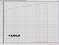
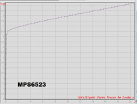
Maybe you could wring a little extra performance out of the first stage by recognizing that the mirror transistors Q3-Q4 never see more than ~ 5 volts of VCE, unlike the source follower transistors Q5-Q21. Allow me to mention the MPS6523 which sells for $0.04 link. It's got higher beta, higher fT, and the same low value of Cob. No quasisaturation at 8mA, whereas the KSA992 just barely starts to quasisaturate. The 6523's Early voltage is about 2/3rds of the 992F's; fortunately your enormous emitter degeneration resistors R7-R8 take care of that quite handily. Datasheet below.
_
_
Attachments
What's an AX6 channel?
This QSA-300 came with two huge transformers, they weigh 14 lbs apiece. The VA rating isn't specified but my goodness they are beastly things. I wonder if you couldn't get 150wpc from this amp with only one transformer installed.
The original filter caps on this one are 10,000uF General Electric metal cans. Internet consensus is that replacing old electrolytics is mandatory and will cure any ills of vintage equipment. I've done enough repairs to know the problem is never electrolytic caps. Is it asking for trouble to press antique caps into service, after they've been stored at god knows what temperature for decades? We'll see. I figure if they survive a few tens of hours of use, they're probably good for a long time.
@MarkJ--
Agreed, I wouldn't actually recommend KSA992 in the current mirror. There are better choices with less quasi-sat.
The real amp is built with 992s, only due to a mistake I made while ordering parts. I was planning to use some spare 2SC6043's which have very low quasi sat (that may have been your data on another thread?)
Well it turns out that the 2SC6043 is NPN and we need PNP here. A minor detail...
I've found the dynaco ST70 putting out 7 watts/ch four times 1970-2010, repaired by replacing plate e-caps. New rectifier tube and output tubes was required twice. PAS2 lost rail voltage twice in that time, needed only caps once, needed caps & rectifier tube also once. I found the 1968 H182 organ amp putting out 7 VAC in 2010, full volume bass channel , restored to 15 VAC with new plate e-caps. (7591 tubes & 5AR4 were fine). I've got three of these, one re-ecapped on the rail by dealer service in 1985. there were many other cathode bypass and other caps failed in these organs, 71 replaced in the top one. Sound checked after every pair replaced, sound or function got better nearly every time. I found a 1980 Allen organ 100 W amp that went silent on Sunday last October, putting out max 2 VAC on speaker on Monday. New rail e-caps, puts out 25 VAC on measured 6 ohm speaker wire. I inherited a Reader's Digest AMFMSHortWave radio bought 197?, worked great then, fuzzy, indistinct, had no sensitivity 2011. Put new e-caps in it, used no alignment tools, it started working great. Using it now.What's an AX6 channel?
The original filter caps on this one are 10,000uF General Electric metal cans. Internet consensus is that replacing old electrolytics is mandatory and will cure any ills of vintage equipment. I've done enough repairs to know the problem is never electrolytic caps. Is it asking for trouble to press antique caps into service, after they've been stored at god knows what temperature for decades? We'll see. I figure if they survive a few tens of hours of use, they're probably good for a long time.
Used NOS e-caps may have tight seals and be full of water, but the tensile strength of non-silicon rubber will be deteriorated by exposure to oxygen. It may take a while for a seal crack to develop and water to evaporate out. "Computer grade" caps from the seventies had a very high ratio of water volume to seal area. BUT, many people that buy old organs without computer grade caps found they work fine for three or four weeks, since the old owners never used them. But then they usually went silent.
My dynaco ST120 has one original channel with an idle current control add on board designed by djoffe. The other channel the idle board blew the sense transistor a second time, went to 220 ma idle current, and removing it broke some TO220 transistor leads in TO5 holes and caused PCB land damage. So I built an Apex AX6 channel for it on bare board with point to point wires. Pictures Retro Amp 50W Single Supply - Page 22 - diyAudio
Last edited:
@indianajo
That AX6 is a fun amp, looks like a nice match for the ST120. Should sound better with the output cap inside the feedback loop.
I have an ST120 on the shelf. It was somebody else's unfinished project. One possibility is to build it as AC coupled with the output caps enclosed in the feedback loop. Another possibility is to build it DC coupled, and use a servo to keep the rails balanced to make up for a lack of a center tap on the transformer secondary. I've done this before and it works great: http://www.diyaudio.com/forums/solid-state/284073-modern-take-sansui-f-1040-amp.html#post4560310
Yah, if I spend time on the -120 it will be to replace the driver boards with completely new ones. The original -120 literature says something about how the design eliminates crossover distortion even with no standing bias current! Guess what? It doesn't do that. It simulates with pretty bad crossover distortion IIRC. It's one of those designs that you have to mod for passable sound and/or reliability.
On July 1st 2017, my friend and I finished assembling a Dynaco QSA-300 from a kit. It sat unassembled in its original box for 41 years until last month.
I recently acquired one of these and have some questions... It looks like the previous owner(s) did the stereo modification but then undid it... and I am not sure if that was to return to original spec or because of some other issue.
I am trying to return it to the stereo config, low impedance mode (for now), which means adding those J1 jumpers and bridging the red output lugs on each side. I am confused because after this was all finished, I could not get it to act properly when wired as the manual suggests i.e. use A and D inputs, nothing on B and C inputs, and then only use outputs A and D for your speakers. The A side works fine and as advertised, but input into D out puts no sound from either C or D outputs... Input into C works i.e. there is output/sound from both C and D outputs.
I didn't wire this machine but I do have the manual/schematics. I can't figure out why they would suggest using A and D inputs. It says that "B and C inputs are disconnected" but I am not sure if that means via circuitry or just what you SHOULD wire it as. From what I can see these are two 150s wired exactly the same but next to each other, so if input B is disconnected (again, not sure what that language referred to) wouldn't D be disconnected? After all, these side by side 150s are not mirrors of each other but rather copy-pasted.
Also, I have the meters x4 with lights installed on this unit.
Anyway, I'm confused, would like it to work as written/ssuggested in the manual, and you are probably the most recent person to build one of these! Any ideas?
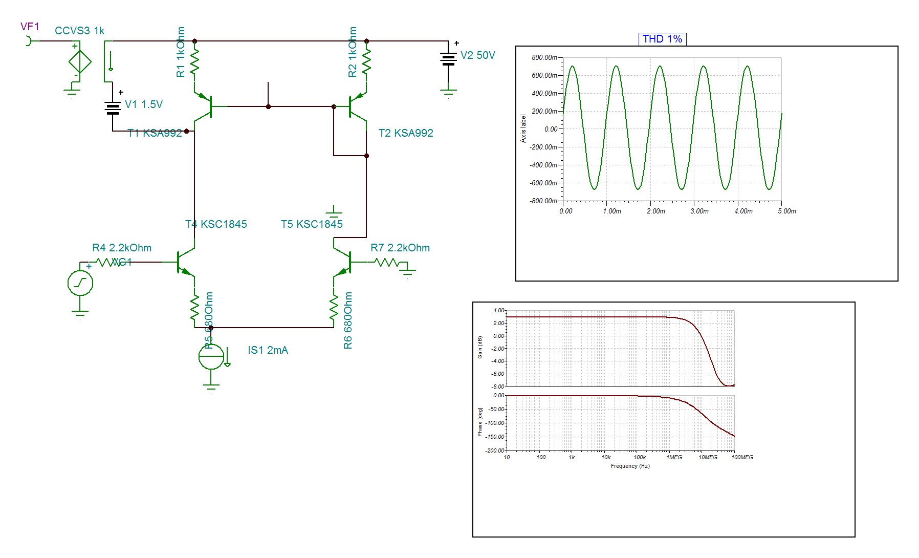
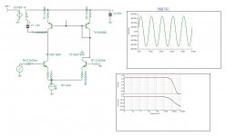
It is worthy to consider the current mirror.
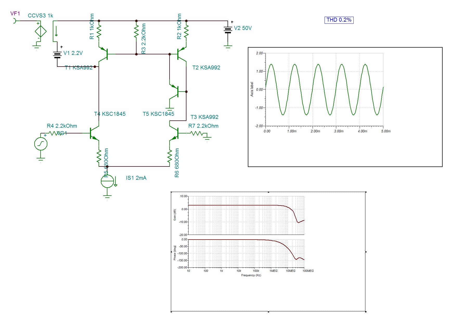
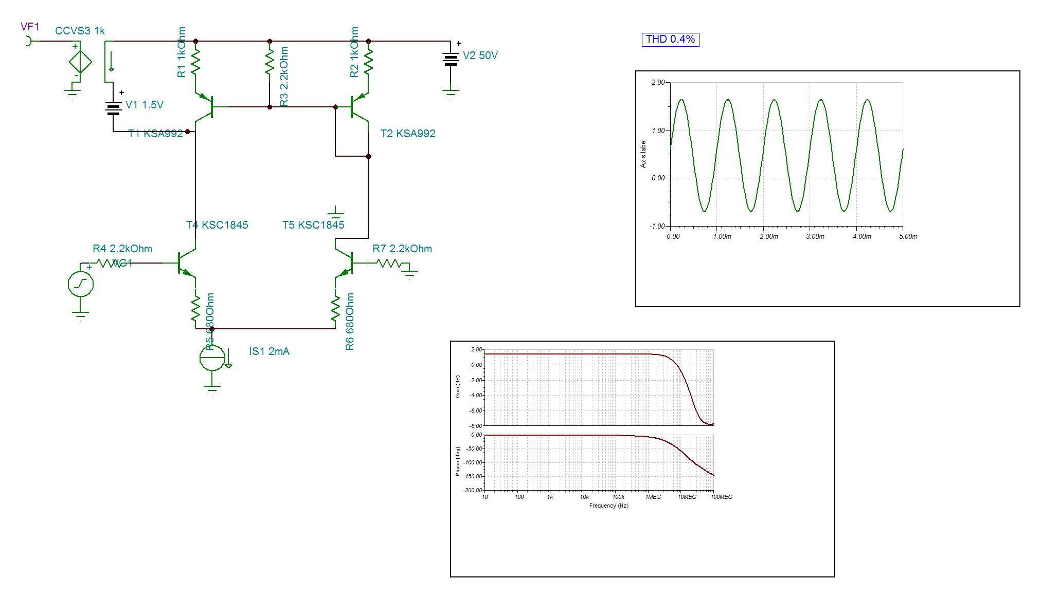
The gain is higher THD is half the frequency response higher.
Without base 2.2k the input is halved to avoid saturation , despite half the output the distortion is double.
The gain is higher THD is half the frequency response higher.
Without base 2.2k the input is halved to avoid saturation , despite half the output the distortion is double.
Attachments
Last edited:
- Status
- This old topic is closed. If you want to reopen this topic, contact a moderator using the "Report Post" button.
- Home
- Amplifiers
- Solid State
- World's youngest and weirdest Dynaco QSA-300 :)