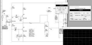
I've always wanted to build a single transistor circuit with a feedback and this is what came out.
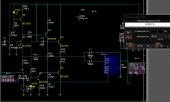
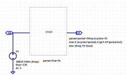
Supply voltage: +-12V (i will use single supply 24V for the prototype)
R3 is not for input LPF, its for simulating a real input source with limited current. There is a LPF too, which uses the source's output impedance as a resistor instead a discrete one.
R8 is because of C7, to not short-circuit the two stages @ high freq.
The feedback divider's current is essential for this circuit.
Its impedance must be as low as possible because there is no emitter follower stage to boost the current like in a LTP circuit.
Attachments
Last edited:
> Single transistor Op-Amp circuit
I'm having trouble counting to "one".
Or wondering "why", when transistors cost less than shipping.
> not short-circuit the two stages @ high freq.
What would be wrong with that? Q1 is a current source. Won't blow-up when shorted.
> feedback divider's current is essential ... Its impedance must be as low as possible
Yes. Or rather you have very little current-gain inside the loop. No current gain from Q1 E to Q1 C. Current gain about 7 in Q2. Even if all of Q2's current went back to Q1 E, that's not heavy NFB.
Q1 E is a 20r load, maybe 25r with your 1K source. That's a heavy load!
To minimize the NFB divider impedance, make it also be the DC load on Q2. You read that current-source loading is "best" but there is always resistive loading. When it is high, CCS loading becomes moot. The real issue here is Q1 E loading. Put ALL of Q2's current through the resistors that flog Q1 E.
Saves a transistor also.
If I were to put that extra part somewhere, I'd buffer the NFB. (LTP is not the only way....)
Resistor in Q2 E makes hand-calc simple, but does not improve linearity as you might think. The increased gain makes-up for junction curve. In fact it starts to work more on the hFE curve than the Vbe curve. hFE is generally more linear over the swing needed for "linear amplification".
However a sim says with Q2 Re=zero, the CE-CE cascade goes lumpy at 30MHz (utterly expected). Some dozen pFd tames that. But may cost more than a resistor. And in gross abuse (fast square waves into 300 foot line!) Q2 can burst of peak current. So 50 or 100 Ohms in Q2 E may be safer and cheaper than a compensation cap.
2Q and 5R. I'm getting about the same 0.05% THD (@ 6V pk) as you. Bias will be stable with device change, room temps, moderate supply change. Input impedance is over 30K, mostly the base resistors. Output impedance is (like yours) much-much less than 1K, probably ~1r (plus output cap) in the audio band.
Attachments
Or wondering "why", when transistors cost less than shipping.
Because its mega cool

> What would be wrong with that? Q1 is a current source. Won't blow-up when shorted.
Yes it wont blow up but gives better AC analys.
> Yes. Or rather you have very little ...
I prefer low impedance divider than a buffer/current_amp stage.
why to add an extra transistor which adds distortion and noise when u have the current to handle the divider.
> Resistor in Q2 E makes hand-calc simple, but does not improve linearity as you might think.
I dont use this R for linearity. I use it to get the same result when I build the prototype. Like in the current mirrors where u can get equal currents with different transistors and high emiter resistors.
Last edited:
Like it very much. 0.008 is veeery enough.
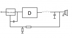
I am going to use this as a "class d linearizer" before a class D amplifier with the fb connected at its output and a capacitor that ensures the fb is not flying at high freq when the LC filter detaches the output.
I am going to use this as a "class d linearizer" before a class D amplifier with the fb connected at its output and a capacitor that ensures the fb is not flying at high freq when the LC filter detaches the output.
Attachments
Last edited:
I count 5 transistors above. Here are two transistors but proven to sound great. Over 100 boards in circulation all over the world. If you want that stick with twenty transistor IC opamps.
Ultralow distortion is not the most important thing in low transistor count CIC third v
http://www.diyaudio.com/forums/group-buys/302859-xrk971-pocket-class-headamp-gb.html

Ultralow distortion is not the most important thing in low transistor count CIC third v
http://www.diyaudio.com/forums/group-buys/302859-xrk971-pocket-class-headamp-gb.html
Last edited:
This is not an op-amp. I like feedbacks and this don't have one.
---
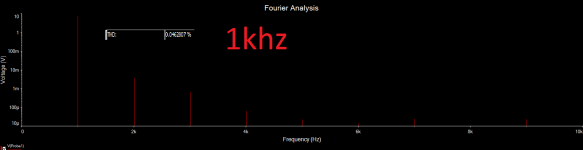
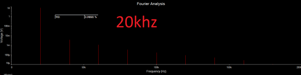
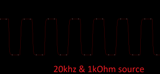
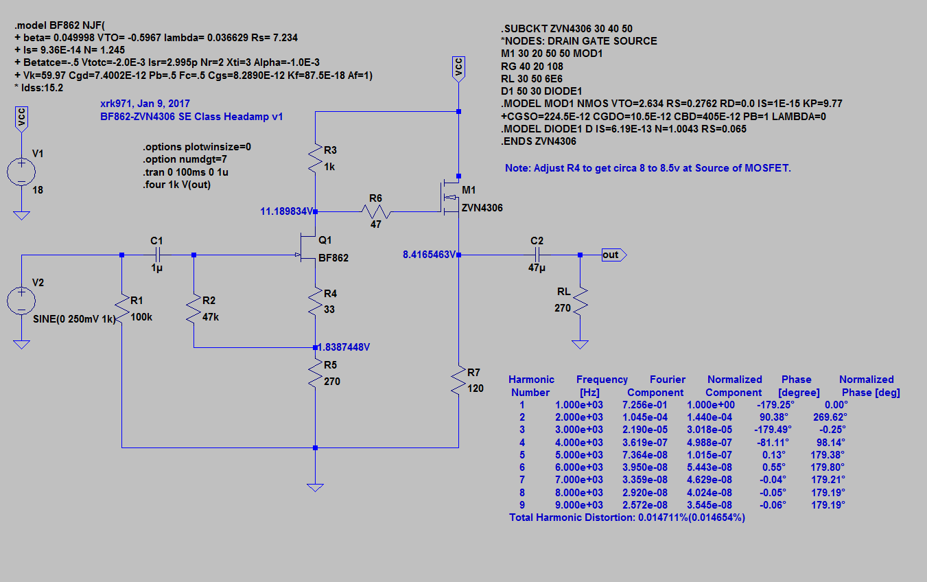
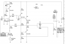
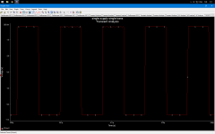
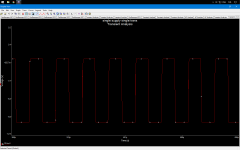
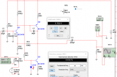
This is my final variant but the squares went weird. They look normal with 47 ohm input but this is unrealistic.
The result is wow: 0.004% 1khz and 0.018 at 20khz
----
edit:
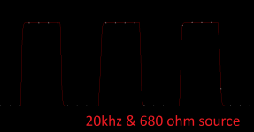
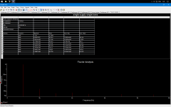
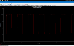
I tried bootstrap+ccs VAS and the squares are fine now.
The THD is even better 0.003 and 0.016 at 20khz
---
This is my final variant but the squares went weird. They look normal with 47 ohm input but this is unrealistic.
The result is wow: 0.004% 1khz and 0.018 at 20khz
----
edit:
I tried bootstrap+ccs VAS and the squares are fine now.
The THD is even better 0.003 and 0.016 at 20khz
Attachments
Last edited:
Two-transistor push-pull (inverting):
http://www.diyaudio.com/forums/solid-state/228913-two-transistor-push-pull-ab-amplifier.html
http://www.diyaudio.com/forums/solid-state/228913-two-transistor-push-pull-ab-amplifier.html
Nice but remember you will have important output DC offset.
"One diode" + whatever drops across R9 if input open or R3 if fed from a DC coupled source, meaning it will pop when plugging/unplugging audio source.
The circuit itself will work, I used to make similar ones looooong ago (think 40 years or so) when "standard" (and practically the only one available) Op Amp was RC741; these discrete ones provided way less hiss and flatter response for Mic inputs in my powered mixers.
Woooow!
I built and tried this one with a headphones: the sound is sooo greeeat!
Very different sound from the other amplifiers I have listened.
I wanted to try the advanced version with the two CCSes and the bootstrap but I dont have other transistors at home.
From previous experiments, I found out that CCS and bootstrap sound different. They both sound good but they are different and I want them both in one great synergy! I can explain only the sound of the bootstrap: SOFT bass, AWSOME GOOD one. I think the synergy of these two is the holy grail.
Now I disconnected the headphones, bypassed R13 with 100 ohm to have less gain and connected it before the class d amp I mentioned to colorify its sound. I wanted to linearize it, not to color it, but I can't take the fb from the class D's out because of the single supply and the decoupling cap.
Very good circuit and the offset is very close to 12V, its 11V which is super (10V in the simulation) and means that the circuit behaves like in the simulator when u use a resistor at every emitter.
----
offtopic:
Strangely, I got 40-50 watts from 24V 1A smps power supply (with the class D amp which is full bridge)
I measured the peaks at the speaker terminal (my multimeter has option to measure peaks) converted that to Vrms, divided by 6 ohms to found out the amperes and multiplied them with the Vrms.
I can't connect a oscilloscope because sparks come out when i connect it and the class D's protection kicks in. Smb know Why this happens ?
I built and tried this one with a headphones: the sound is sooo greeeat!
Very different sound from the other amplifiers I have listened.
I wanted to try the advanced version with the two CCSes and the bootstrap but I dont have other transistors at home.
From previous experiments, I found out that CCS and bootstrap sound different. They both sound good but they are different and I want them both in one great synergy! I can explain only the sound of the bootstrap: SOFT bass, AWSOME GOOD one. I think the synergy of these two is the holy grail.
Now I disconnected the headphones, bypassed R13 with 100 ohm to have less gain and connected it before the class d amp I mentioned to colorify its sound. I wanted to linearize it, not to color it, but I can't take the fb from the class D's out because of the single supply and the decoupling cap.
Very good circuit and the offset is very close to 12V, its 11V which is super (10V in the simulation) and means that the circuit behaves like in the simulator when u use a resistor at every emitter.
----
offtopic:
Strangely, I got 40-50 watts from 24V 1A smps power supply
(with the class D amp which is full bridge)I measured the peaks at the speaker terminal (my multimeter has option to measure peaks) converted that to Vrms, divided by 6 ohms to found out the amperes and multiplied them with the Vrms.
I can't connect a oscilloscope because sparks come out when i connect it and the class D's protection kicks in. Smb know Why this happens ?
Attachments
Last edited:
- Status
- This old topic is closed. If you want to reopen this topic, contact a moderator using the "Report Post" button.
- Home
- Amplifiers
- Solid State
- Single transistor Op-Amp circuit