"PE" ?
The setup is:
24V 1A smps from printer feeds the class D amp which is full bridge and phase A goes to +, phase B goes to - terminal.
this smps goes to 220V via 2 wires, not 3 like in PC ATX supply.
the OSC goes to 220V via 3 wires.
I don't think this is the problem. Very strange one.
I think it could be from: some smps-es have a capacitor which connects the primary's and the secondary's grounds together at HF.
Last edited:
He´s using a class D amp which has bridged outputs. The black speaker terminal is not ground of course.
That you can't (shouldn't) connect a grounded scope when the amplifier is also grounded from somewhere else - which, if it's not the power supply, may be the signal source you're using. When doing so, you would be shorting out that side of the power amp.
EEVblog #279 - How NOT To Blow Up Your Oscilloscope!
EEVblog #279 - How NOT To Blow Up Your Oscilloscope!
The scope ground probe connects direct to the mains PE.
It is NOT ISOLATED.
For the safety of the operator, the scope ground probe must NEVER be modified to isolate it form PE.
It is NOT ISOLATED.
For the safety of the operator, the scope ground probe must NEVER be modified to isolate it form PE.
The scope ground probe connects direct to the mains PE.
It is NOT ISOLATED.
For the safety of the operator, the scope ground probe must NEVER be modified to isolate it form PE.
And what happens ?
PC is isolated,
the smsp of the amp too
I have a modified power cable for the scope and tried with it but again the same.
Its better but again not cool.
What kind of "PC" does not have a protective earth connection? The only stationary one I can think of would be a Mac Mini, otherwise there's any number of LapNoteNetTopBooks, of course.
Anyway, you might be running into the peculiarities of switch-mode power supplies or rather the obligatory EMI filtering here. In any SMPS (*) you'll find several nF worth of capacitance from secondary-side ground to PE, secondary ground to either phase or neutral, or between phase and neutral and PE which connects to secondary-side ground. That's hundreds of kOhms at 50 Hz, a lot less at multiple kHz.
*) Well, any that has any hope of conforming to EMI regulations. I recently looked at the fluorescent lamp driver from an early-2000s kitchen under-counter lamp that had failed and ended up in my parts box, and not only did I find the likely cause of failure - it's a capacitive dropper supply, and the 33 nF cap was only measuring 17.8 nF - but was shocked by the total lack of any kind of EMI suppression components. We're talking a 20W-ish lamp here if memory serves, and not a very cheap kitchen either. Not even a filter cap, let alone common-mode chokes or other such fancy stuff. Just a tubular fuse. Back in the day I used to be annoyed every time this thing was used because I wanted to listen to my shortwave radio upstairs from it! The only thing even worse was the bloody plasma TV - Panasonic ultimately switched to electrically shielded panels when the technology was already on its way out, but this one like most plasmas was from before that.
Member
Joined 2009
Paid Member
Woooow!
I built and tried this one with a headphones: the sound is sooo greeeat!
Very different sound from the other amplifiers I have listened.
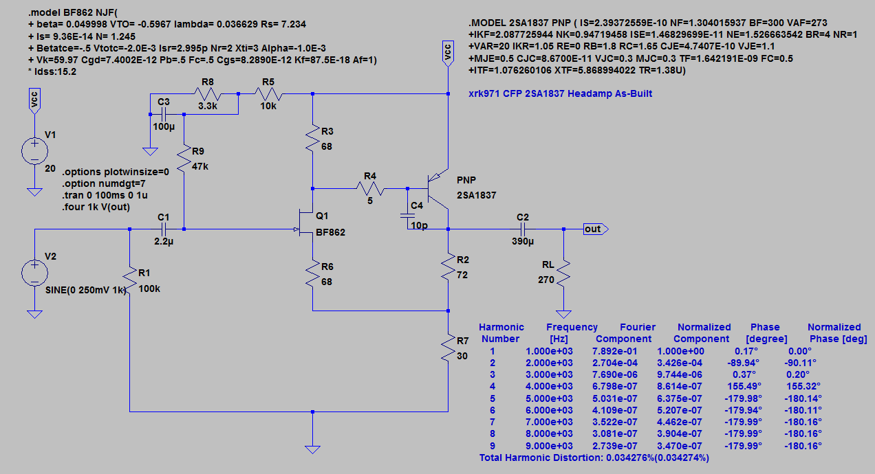
Looks like a CFP with gain loaded on a CCS - nice. My only headphone amp project needed no voltage gain but I also used a CFP loaded on a CCS. I found it was very similar to the circuit of a Naim pre-amp.
http://www.diyaudio.com/forums/headphone-systems/275180-grasshopper.html
What kind of "PC" does not have a protective earth connection? The only stationary one I can think of would be a Mac Mini, otherwise there's any number of LapNoteNetTopBooks, of course.
Yes, I forgot that.
Looks like a CFP with gain loaded on a CCS - nice.
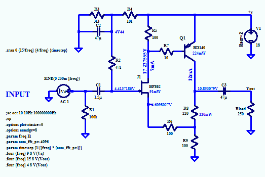
Yea, look this one:
Supply voltage: +-12V
Offset: 200mV
OPS bias current: 300 pA
THD: 0.040% at 20k
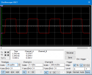
Squares: beautyful ones!
The feedback divider is that low because Im using it as load in the simulation.
C1 is not for compensation, this circuit has compensation only at the output transistors because they are a VAS too and have very high voltage gain.
I think this is better than LTP because in LTP the feedback goes thru a transistor which slows it. Im going to build it but using a CCS + Bootstrap bombination. *combination.
Attachments
Last edited:
Your black terminal is NOT repeat NOT ground, but HOT out of phase, so you are shorting one side of your bridged amp to ground.?
I connect it to the black terminal of the speaker.
So n ow you know why it sparks and mutes 😉
Why do you say so?How is this possible when the scope, the PC and the SMPS are galvanically separated ?
As soon as any part of the scope is connected to an amp which is fed from a power supply or battery, all 3: Amp, Scope and Supply are NOT galvanically separated any more.
Unless you use isolation caps ... which you didn´t even mention so I suppose not there.
Woooow!
I built and tried this one with a headphones: the sound is sooo greeeat!
Very different sound from the other amplifiers I have listened.
I wanted to try the advanced version with the two CCSes and the bootstrap but I dont have other transistors at home.
From previous experiments, I found out that CCS and bootstrap sound different. They both sound good but they are different and I want them both in one great synergy! I can explain only the sound of the bootstrap: SOFT bass, AWSOME GOOD one. I think the synergy of these two is the holy grail.
Now I disconnected the headphones, bypassed R13 with 100 ohm to have less gain and connected it before the class d amp I mentioned to colorify its sound. I wanted to linearize it, not to color it, but I can't take the fb from the class D's out because of the single supply and the decoupling cap.
Very good circuit and the offset is very close to 12V, its 11V which is super (10V in the simulation) and means that the circuit behaves like in the simulator when u use a resistor at every emitter.
----
offtopic:
Strangely, I got 40-50 watts from 24V 1A smps power supply 😀 (with the class D amp which is full bridge)
I measured the peaks at the speaker terminal (my multimeter has option to measure peaks) converted that to Vrms, divided by 6 ohms to found out the amperes and multiplied them with the Vrms.
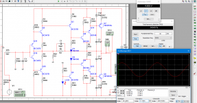
I can't connect a oscilloscope because sparks come out when i connect it and the class D's protection kicks in. Smb know Why this happens ?
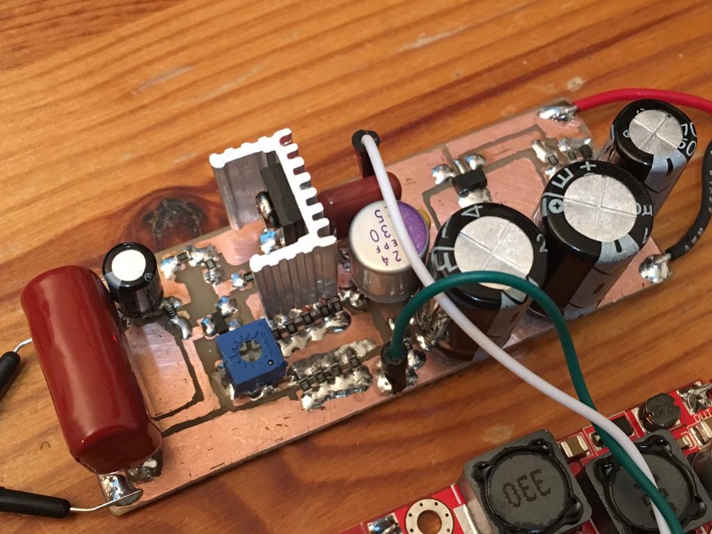
This topology does indeed sound very good. I have a similar amp using a JFET in input stage and 2SA1837 in CFP with a resistor current sink. It's my best sounding headphone amp. Currently my reference standard for sound quality. Built with Aksa's help on the design.
Here is a prototype to that amp using a BD140 in a CFP with gain.
Also very sweet sounding.
Yes this is good and it looks like my design with the difference that my design is CCS loaded.
It seems that CFP is an opamp.
It seems that CFP is an opamp.
It seems that nobody tried this compensation.
It doesn't load the input stage and actually disloads it because Ic of Q4 goes small and this makes the Rbe of Q4 higher.
The third attachment is without it.
It would be an interesting to combine it with 1-2p Cdom.
Now im looking into VAS stage with its own feedback divider.
Then the compensation will be a cap over the one of the resistors.
Attachments

Last edited:
- Status
- Not open for further replies.
- Home
- Amplifiers
- Solid State
- Single transistor Op-Amp circuit