After sucessfully building two very different power amps sporting lateral mosfets on the OPS I feel much more confident to use the same OPS with other front ends.
Used to the sound of my old meridian 103 I would like to clone it and use laterals on the output.
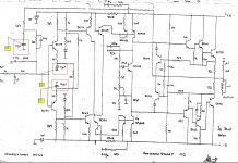
Allready started the simulation and got stuck with too low gain.... So I decided to post my work here hoping to gather enough interest and so start developing this new project.
Used to the sound of my old meridian 103 I would like to clone it and use laterals on the output.
Allready started the simulation and got stuck with too low gain.... So I decided to post my work here hoping to gather enough interest and so start developing this new project.
Attachments
If you are "into" Meridian stuff, I believe I have an original 103 board. I also have 2 x 101 preamp.
Regards
Roar
Regards
Roar
I do have one working original 103.... What I want is to replicate it with a different OPS.
The 103 is one of the sweetest amps I had the oportunity to listen to so maybe I can have the same results with a DIY build.
The 103 is one of the sweetest amps I had the oportunity to listen to so maybe I can have the same results with a DIY build.
Not much happened today.... will revisit the sch tomorrow.
Wonder why this sch does not get your attention.
Need to decide what are the best bjt to use in the IPS and on the vas....
Wonder why this sch does not get your attention.
Need to decide what are the best bjt to use in the IPS and on the vas....
The front end of the 103 schematic is similar to many CFA type designs shown here. Member Lazy Cat's variations on his VSSA amplifier design are good examples of the topology and show suitable available parts choices. Most variations on it already have a Lateral Mosfet output stage matched correctly to the front end anyway and builders seem to agree that even the basic "First One" is a great sounding simple amp in its own right. Lazy Cat's own preferred version has been built, tested in audiophile comparisons and boards sold commercially in SMD format too.....Wonder why this sch does not get your attention....Need to decide what are the best bjt to use in the IPS and on the vas....
In the case of the 103, feedback is brought back to the bases of the input devices and not to the emitters. The bases are high impedance so I do not know if we can call it a CFA.
In the case of Lazy Cat's VSSA http://www.diyaudio.com/forums/vendors-bazaar/225747-vssa-lateral-mosfet-amplifier.html the feebback is fed into the emiters of the IPS.
In the case of Lazy Cat's VSSA http://www.diyaudio.com/forums/vendors-bazaar/225747-vssa-lateral-mosfet-amplifier.html the feebback is fed into the emiters of the IPS.
Here we have the same concept... feedback to IPS emitters: http://www.diyaudio.com/forums/solid-state/210116-tssa-simplest-symmetrical-amplifier-2.html
Ifo about CFA:
Originally Posted by Bob Cordell View Post
Hi Richard,
I think we need to be careful to distinguish current-mode analog signal processing from current feedback amplifiers. In a CFA the signal feedback can be considered a current, but that is all there need be in the current domain. Put another way, in a CFA the error amplifier reacts ideally to a difference (error) of currents, while in a VFA the error amplifier reacts to a difference (error) in voltages. The impedance that the feedback network sees at the error amplifier is largely what differentiates the two. The CFA feedback network sees a low impedance ideally, while the VFA feedback network sees a high impedance ideally.
It is important to realize that the voltage at the feedback node of a CFA is not necessarily zero; it is often equal to the input voltage to the amplifier, as in a non-inverting CFA. But you can also view the CFA feedback network as operating as a voltage divider that seeks to produce a voltage that is the same as the input voltage for a non-inverting CFA. If it does not produce the same open-circuit voltage, then an error current will flow. There can be many ways to look at this. Sort of like how given source and network has Thevenin and Norton equivalents. In fact, I seem to recall CFAs as being described as Norton amplifiers. I could be wrong about that, however.
I think that the classic RIAA preamp, wherein the RIAA feedback network connects to the emitter of the input transistor, is in fact a CFA.
I hope that my assertion that the CFA can be viewed in more than one way has not confused matters.
A better example of current-mode analog signal processing is the cascomp input stage, where the signal current from an input LTP is summed with an error correction current at the emitters of a cascode.
Cheers,
Bob
Hi Bob. Not too sure about the resistor values you have changed at the input stage.
From what i understand, this being an inverting nfb amp, places the input pair bases at virtual ground. Looking at the original circuit the input impedance is then 11k and there is a T-network in the feedback loop, only the value of the resistor in series with C1 is not shown. Your modified values do raise the closed loop gain but also reduce the input impedance excessively.
From what i understand, this being an inverting nfb amp, places the input pair bases at virtual ground. Looking at the original circuit the input impedance is then 11k and there is a T-network in the feedback loop, only the value of the resistor in series with C1 is not shown. Your modified values do raise the closed loop gain but also reduce the input impedance excessively.
BTW
My name is Ricardo
The post 10 was taken from another thread and it belongs to Bob Cordell... I posted it here to justify my doubts about this being or not a CFA
My name is Ricardo
The post 10 was taken from another thread and it belongs to Bob Cordell... I posted it here to justify my doubts about this being or not a CFA
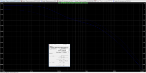
Open loop gain, or closed loop gain?............. got stuck with too low gain......
Hello andrew
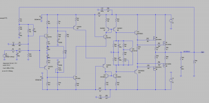
Did some work this morning so now i have 26db closed loop.
Will post a sch latter hoping you would comment on it
Did some work this morning so now i have 26db closed loop.
Will post a sch latter hoping you would comment on it
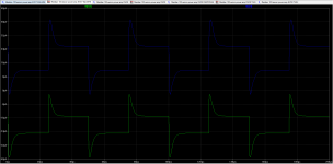
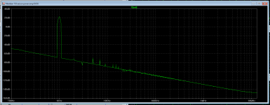
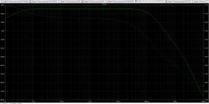
Today I managed some free time for this.
I believe I am getting good results now...
I believe I am getting good results now...
Attachments
- Home
- Amplifiers
- Solid State
- Meridian 103 clone