For those that did not follow this thread... It is a Meridian clone using laterals for OPS.
The results are so amazing I am wondering if they are correlated with reality.
The results are so amazing I am wondering if they are correlated with reality.
Attachments

Personally I would replace the 10nF drain caps with 2.5mm 47uF lytics. The funny thing about lytics is that they usually already have a 10nF or so cap inside them which bypasses the ESR at high enough frequencies where the oxide layer behaves more like a dielectric than a conductor. At low lead spacings the inductance is often not a concern and the lossiness does nothing but reduce resonances which low-loss caps tend to exacerbate.
The 470nF+4.7R snubbers can be replaced with a single 470uF lytic if you use the 47uF drain caps, although for the current 10nF drain caps they might be in the right ballpark for damping them IF there are no other lytics on the board connected across the power rails.
Just my 2C, although the current arrangement may work just fine. I just prefer to have a lot of capacitance on the board close to the output transistors as this keeps most of the haversines confined to a small area.
What is it in the circuit that makes the 103/105 so 'fast'? I have not heard such transparency from any other product since these were introduced in 1977.For those that did not follow this thread... It is a Meridian clone using laterals for OPS.
The results are so amazing I am wondering if they are correlated with reality.
Personally I would replace the 10nF drain caps with 2.5mm 47uF lytics. The funny thing about lytics is that they usually already have a 10nF or so cap inside them which bypasses the ESR at high enough frequencies where the oxide layer behaves more like a dielectric than a conductor. At low lead spacings the inductance is often not a concern and the lossiness does nothing but reduce resonances which low-loss caps tend to exacerbate.
The 470nF+4.7R snubbers can be replaced with a single 470uF lytic if you use the 47uF drain caps, although for the current 10nF drain caps they might be in the right ballpark for damping them IF there are no other lytics on the board connected across the power rails.
Just my 2C, although the current arrangement may work just fine. I just prefer to have a lot of capacitance on the board close to the output transistors as this keeps most of the haversines confined to a small area.
Thank you, I will try those mods.
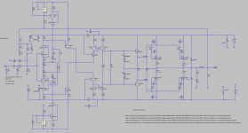
Would you please comment on the diodes D2 and D4 as I am not sure what these are for.... would BAV21 be better here ?
What is it in the circuit that makes the 103/105 so 'fast'? I have not heard such transparency from any other product since these were introduced in 1977.
Yes, the original 103 is fast but lean.
Wondefull highs.... I will see what it does with laterals on the output 🙂
I have two pairs of 105s I've been contemplating on paralleling. That would probably have a bit of an impact.Yes, the original 103 is fast but lean.
Wondefull highs.... I will see what it does with laterals on the output 🙂
I can't determine what D2 and D4 are for, but I would think they have something to do with tuning the amp behavior during startup or prolonged clipping. They seem to be keeping the input transistors slightly on at low supply voltages. They could also be affecting temperature compensation.
The funny thing about lytics is that they usually already have a 10nF or so cap inside them which bypasses the ESR at high enough frequencies where the oxide layer behaves more like a dielectric than a conductor.
I have never heard such a tale, where do you get your information, I am curious?
It is there in some obscure capacitor manufacturer app notes which discuss the electrolytic equivalent model to higher detail. If you measure the ESR of a lytic you will find it starts to decrease above a certain frequency. You can see it here on page 8:
http://www.hoffmann-hochfrequenz.de/downloads/experiments_with_decoupling_capacitors.pdf
In this case it's more like 1nF, but it's still there. It looks like I didn't save the original references.
http://www.hoffmann-hochfrequenz.de/downloads/experiments_with_decoupling_capacitors.pdf
In this case it's more like 1nF, but it's still there. It looks like I didn't save the original references.
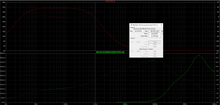
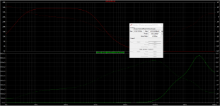
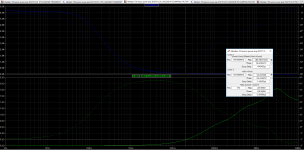
New work done.
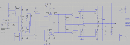
Jfet cascoded IPS
IPS bias now set with CCS found here: TSSA - The Simplest Symmetrical Amplifier
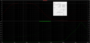
Needed to reduce lead lag capacitor in the feedback loop to retain a good phase lag.
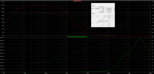
That also increased bandwidth and -3dB is now near 300khz.
IPS emitter decoupling capacitors where increased to 1000u.
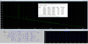
THD reduced from 0.005 to 0.0035% ...
Now my question is... can I use 62V rails with only two output lateral mosfets per rail or should I reduce voltage ?
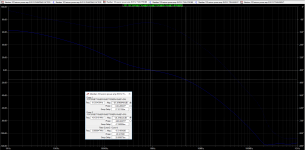
Is it normal that I find a damping factor of 33000 at 1khz ?
Output impedance is 247uohm at 1khz .... never simed nothing like it before.
Jfet cascoded IPS
IPS bias now set with CCS found here: TSSA - The Simplest Symmetrical Amplifier
Needed to reduce lead lag capacitor in the feedback loop to retain a good phase lag.
That also increased bandwidth and -3dB is now near 300khz.
IPS emitter decoupling capacitors where increased to 1000u.
THD reduced from 0.005 to 0.0035% ...
Now my question is... can I use 62V rails with only two output lateral mosfets per rail or should I reduce voltage ?
Is it normal that I find a damping factor of 33000 at 1khz ?
Output impedance is 247uohm at 1khz .... never simed nothing like it before.
Attachments
-
Meridian 103 exicon power amp EVO15 CCS IPS CSCODE TIAN PROBE.asc18.7 KB · Views: 71
-
Meridian 103 exicon power amp EVO15 CCS CASCODE IPS RESPONSE.asc17.1 KB · Views: 67
-
Meridian 103 exicon power amp EVO15 CCS CASCODE IPS DAMPING FACTOR.asc17.8 KB · Views: 70
-
Meridian 103 exicon power amp EVO15 CCS IPS CASCODE TRANSIENT.asc17.4 KB · Views: 70
-
 EVO15 CCS CASCODE IPS.PNG65.7 KB · Views: 227
Last edited:
Adjusted bias current to much lower and acceptable values.
Adding some additional info for those who do not have the models.
Just place everything in the same directory and open with LTSpice....
Adding some additional info for those who do not have the models.
Just place everything in the same directory and open with LTSpice....
Attachments
Output impedance can be down in the uohms depending on the feedback, but this is moot as one inch of wire swamps it out.
At 20KHz there is nothing to damp, the speaker parasitics are preventing any damping from taking place through the voicecoil at those frequencies. If you look at the numbers, the more likely reason if the output inductor affects sound is that it causes some HF rolloff. And/or it is preventing oscillation or RF demodulation.
At 20KHz there is nothing to damp, the speaker parasitics are preventing any damping from taking place through the voicecoil at those frequencies. If you look at the numbers, the more likely reason if the output inductor affects sound is that it causes some HF rolloff. And/or it is preventing oscillation or RF demodulation.
- Home
- Amplifiers
- Solid State
- Meridian 103 clone