Greetings,
I've been quite interested in diy for several years now, yet I'm still relatively inexperienced with amplifier design and construction. You see, I've designed and built using only op-amps to date.
Recently, I've been trying to design a preamplifier using BJTs. I've laid out some goals for myself: High input impedance, wide bandwidth (DC to 50kHz+), very little negative feedback (I'm not too worried about THD), relatively low output impedance and as little noise from the power supply as possible.
With these goals in mind I settled on a balanced topology with emitter-follower buffers for an output stage. Since my only source is unbalanced, I've been considering a simple emitter-follower buffer as an input stage followed by differential pairs.
I then proceeded to simulate my ideas using what limited simulation software I have. Unfortunately, the only result is that I've had considerable difficulty with my gain stage. After many attempts to design a functional gain stage and just as many stiff necks and sore wrists, I decided to go to the experts.
So I ask you, can you either point me in the direction of a similar preamp, generally accepted for its high quality, or give me a little advice.
Thanks,
Stephen
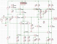
trial schematic
Thanks for your interest, Mr. Pass.
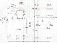
This is my latest design, one of several trial schematics. This should give you a good idea of my desired topology. R21 represents the load.
As I stated before, I think my problem is the gain stage. This design seemed to be unaffected by the feedback loop. I played around with the values for a while with no improvement.
Any advice/criticism is welcome.
Thanks,
Stephen
Thanks for your interest, Mr. Pass.
This is my latest design, one of several trial schematics. This should give you a good idea of my desired topology. R21 represents the load.
As I stated before, I think my problem is the gain stage. This design seemed to be unaffected by the feedback loop. I played around with the values for a while with no improvement.
Any advice/criticism is welcome.
Thanks,
Stephen
Attachments
If i was you i would start removing Q4,5,6 add two emitter of 100Ohm on Q2 and Q3.
Remove C4 and C5.
Remove the Feedback network. Place Q3's base on ground.
Add two 10k resistors two ground from the collector of Q7 and Q8.
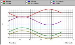
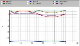
When you have done this. Try simulate again and look on current and DC level through the design. Look at gain and phase respone. Look at the output signal to see if it clips. If it clips is it even or uneven...
Sonny
Remove C4 and C5.
Remove the Feedback network. Place Q3's base on ground.
Add two 10k resistors two ground from the collector of Q7 and Q8.
When you have done this. Try simulate again and look on current and DC level through the design. Look at gain and phase respone. Look at the output signal to see if it clips. If it clips is it even or uneven...
Sonny
Oops!
I forgot to metion a couple of things:
1. Originally, there were no resistors attached to the emmiter of Q3. Q8 was being driven by Q6. I tried the present configuration for the sake of curiosity and forgot to change it back.
2. My choice of transistors in this simulation was limited to a list of about 5, so I may end up using different devices. However, if you believe the BCs will do fine, I'd be happy to use them.
Sonny
I'll make the changes you suggested tonight when I get home from work and let you know.
Thanks,
Stephen
Start getting the circuit working with the BC types, then you can change them later and try new sims. Should be easier this way.
The thing i asked you to do will remove the feedbackloop.
Your problem could be addressed to a gain that is greater than or equal to one at the frequency where the phase through the amplifier turns 180 degress compared with the input signal.
Sonny
The thing i asked you to do will remove the feedbackloop.
Your problem could be addressed to a gain that is greater than or equal to one at the frequency where the phase through the amplifier turns 180 degress compared with the input signal.
Sonny
Jocko,
I'm not familiar with the term degeneration. Could you please specify?
Regarding gain: I have an old Bryston 4B Pro with aged power transformers. When paired with my current preamp, I can't adjust the volume pots of the 4B above half or the hum through my speakers becomes noticeable. For that reason I would like to have a reasonable amount of gain. I was hoping for about 6dB.
Stephen
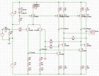
mmhh .. Stephen you have to turn Q2 and Q3 upside down. So that their emitter run through a 1320 Ohm resistor and tied together at the collector of Q1.
Do you get it?
Then Change r4,r5,r25 and to a r7,r28,r29 resistor of 220ohm*3*2 = 1320Ohm.
Change r22 and r23 to a resistor of 220Ohm.
Then change r13 and r14 to resistor of 1k1.. Then each of the outputs should have a gain of ~5. and they should be balanced.
By the way reduce r8 (330k) down to 10k - 100k. By doing this you reduce the offset voltage between the 2 outputs.
I hope that this not messes up you idear to much!?
Sonny
The reason the differential pair is 'upside-down' is because I wanted a very high input impedance. Essentially a buffer. With that in mind, could you suggest a modification to the gain stage instead of the differential pair to acheive some gain?
Sonny and Jocko,
I'll make the changes you suggest and post the results. But would it be acceptable to keep my 'upside-down' differential pair and use it to drive a second 'right-side-up' differential pair?
Thanks for the help,
Stephen
Sonny and Jocko,
I'll make the changes you suggest and post the results. But would it be acceptable to keep my 'upside-down' differential pair and use it to drive a second 'right-side-up' differential pair?
Thanks for the help,
Stephen
You need some way to make sure that the collector of those two are at, or near ground. A small mismatch in current will make it go full tilt to either rail. You could do all your gain in the diff amp, and stick followers after it. Capacitor couple the output, and be done with it.
E-mail me if you have serious questions.
(This is why I hate this simulation crap. You plug in something that probably won't work, and get something back that is equally nebulous. It ought to be giving you an red flag like: "Turn the ship upside down, Unk!") End of rant. Not to be taken personal.
Jocko
If you use the emitter follower as you suggested (with some modification to get it working) you will not be able to split the signal into two signals with one in phase and one turned 180degress around.
Thats the good thing of a diff amp and it keeps you circuit simple.
When using a diff amp with emitter resistors in the area of 1k - 3k as you have done the diff amp will have a high input impedance.
The reason for 2k7 and 2k5 and not two identical values is due to the base current flowing in Q2 and Q3. Try lowering the input resistor from 100k down 10k and you will see a shift in the offset voltage.
But go for it.. Try use your imagination and use the simulator to see how it turns out. It is cheaper then burning components.
")
Sonny
Thats the good thing of a diff amp and it keeps you circuit simple.
When using a diff amp with emitter resistors in the area of 1k - 3k as you have done the diff amp will have a high input impedance.
The reason for 2k7 and 2k5 and not two identical values is due to the base current flowing in Q2 and Q3. Try lowering the input resistor from 100k down 10k and you will see a shift in the offset voltage.
But go for it.. Try use your imagination and use the simulator to see how it turns out. It is cheaper then burning components.
Sonny
- Status
- This old topic is closed. If you want to reopen this topic, contact a moderator using the "Report Post" button.
- Home
- Amplifiers
- Solid State
- Good design practice