Hi,
I just completed my first SKA GB150D amp (PCB from Jim's audio) and am experiencing some problems adjusting the bias current. Both with the input open or shorted, the bias current reacts extremely sensitively to the variable resistor adjustment and jumps somewhat sporadically. It is possible to set it into a reasonable range, but as one crosses the threshold, a quite significant additional background appears. Also, crackles can be heard when turning the potentiometer above the threshold.
Is this a typical sign that the amp is oscillating and is there any simple way to find that out without an oscilloscope?
Sure you have oscillation problem.Hi,
I just completed my first SKA GB150D amp (PCB from Jim's audio) and am experiencing some problems adjusting the bias current. Both with the input open or shorted, the bias current reacts extremely sensitively to the variable resistor adjustment and jumps somewhat sporadically. It is possible to set it into a reasonable range, but as one crosses the threshold, a quite significant additional background appears. Also, crackles can be heard when turning the potentiometer above the threshold.
Is this a typical sign that the amp is oscillating and is there any simple way to find that out without an oscilloscope?
Connect resistors INSTEAD OF FUSES and a lamp in series with transformer primary coil .I can't see an easy way to resolve this problem without a scope🙁
Try to increase the compensation capacitors and see what happened.
Last edited:
You can pick up a cheap scope on ebay.
I got one for £40 because it had a faulty second channel but worked fine on channel 1.
I have had it for a good few years now and not had any problems.
I really couldn't work without one.
I got one for £40 because it had a faulty second channel but worked fine on channel 1.
I have had it for a good few years now and not had any problems.
I really couldn't work without one.
I remenber a problem with this amplfier ... to get rid of oscillation I had te expand bandwith by reducing capacitor in feedback circuit ....
Are you trying to adjust bias with the speakers connected? If you can hear crackling whilst adjusting bias, it sure seems like it and that is absolutely the wrong procedure.
All amplifier DC adjustments are performed without a load i.e no speakers and no input signal connection at all. Your amplifier may not be so bad after all.
All amplifier DC adjustments are performed without a load i.e no speakers and no input signal connection at all. Your amplifier may not be so bad after all.
I adjusted the bias current and DC offset without a load and only connected a cheap test speaker thereafter. Only then, when I was playing around with the bias setting, I noticed this.
Thanks guys, I'll try adjusting the feedback capacitor and will get an oscilloscope soon. Will hopefully let you know then whether it worked.
Sure you have oscillation problem.
Connect resistors INSTEAD OF FUSES and a lamp in series with transformer primary coil .I can't see an easy way to resolve this problem without a scope🙁
Try to increase the compensation capacitors and see what happened.
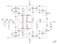
Just to make sure: you're talking about C3 in this diagram?
I tried doubling the capacitance (using a ceramic), but to no avail.
Can anyone suggest a good and systematic guide / website on the background and possible sources of amplifier oscillation? Of course it is quite a ubiquitous phenomenon, but the information I could find seems quite scattered of the "I observe this" and "try this as a fix" type. I'm more interested in a general introduction / discussion with some examples.
In this design, what would be the most significant inductive component in the oscillator?
The feedback capacitor in parallel to the main feedback resistor can make an amplifier more stable or less stable.
Start without any capacitor and examine the 1kHz square wave response.
Then try a small value of ~5pF to see what effect it has on overshoot and ringing.
Try increasing in small steps to ~22pF to see what is happening.
Then repeat with resistive loading (4r0, 8r0, 16r) and then repeat with C||R loading. C from 1nF to 1uF in small steps. A switched capacitor bank is much quicker.
Some recommend that C3 be an R+C with R = variable resistor.
Trim the squarewave for best square shape by varying the VR. Then replace with fixed resistor.
Last edited:
Still without a scope, I tried a range of feedback capacitors from zero to 100pF, but the oscillatory behavior remains throughout. I also double-checked all components and resoldered all joints to rule these options out.
I should have access to a scope soon. Once I have established that it indeed oscillates, what are the subsequent debugging steps one can take? Maybe someone knows of a good site / thread on this topic?
I should have access to a scope soon. Once I have established that it indeed oscillates, what are the subsequent debugging steps one can take? Maybe someone knows of a good site / thread on this topic?
the SKA Forum
he can not go into ska forum, if he has jims audio boards and not boards original from greg
http://www.diyaudio.com/forums/solid-state/238593-ska-gb150d-now-public-domain.htmlMaybe someone knows of a good site / thread on this topic?
http://www.diyaudio.com/forums/solid-state/239418-tgm7-amplifier-based-greg-ball-ska.html
I assembled a second independent board with slightly different components, since I couldn't track down the source of oscillation in the first one.
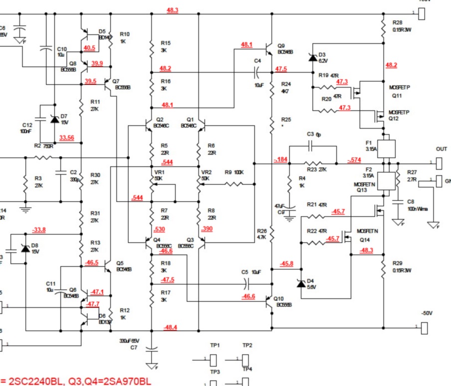
The new one does not oscillate, one can adjust the bias current very steadily, but this time I cannot get the DC offset below 460mV. It does respond to adjusting VR2, I only 'run out of headroom', i.e. reach the limit of the trimmer before it is zero. I'm running the circuit with +-37V instead of the specified +-50V, but I think this should be within the operating range.
A schematic with the voltages (all relative to power ground) in the first stage is attached, since I would guess the source of the problem lies here (?). Some of the base-emitter voltage drops seem a bit on the low side (Rod Elliott mentioned that they should be around 600-700mV), but I'm unsure whether this is a cause or a symptom. Is it obvious to anyone what the source of the DC offset may be from this or are potentials at other nodes required?
Instead of the BC556C and BC546C I used on the first board, I switched to the 2SC2240BL and 2SA970BL now (keeping the different lead convention in mind).
Attachments
- Status
- Not open for further replies.
- Home
- Amplifiers
- Solid State
- Problems adjusting bias current on SKA GB150D