I am a little confused about how to wire
- PSU ground
- speaker ground
- signal ground
- mains earth
Is it a typical star ground?
Which one of these would be the correct way?
Here is what the amp board looks like..

Thanks
- PSU ground
- speaker ground
- signal ground
- mains earth
Is it a typical star ground?
Which one of these would be the correct way?
Here is what the amp board looks like..
Thanks
Attachments
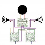
From an electrical point of view I see no differences between the schemas. In version 1 you connect the cables at the blocks and in the second one you split the cables later on. Both schemas will work, use the one that suits/looks best.
Regars
Kpax
Regars
Kpax
thanks KPAX for your reply! I am waiting for a couple of components to arrive before I can wire this up 🙂
Dakku,
You'd better select ONE point (on your enclosure) and call that "ground". Next, you connect the PSU, the amps and the speakers directly to that point, no exceptions!
The audio inputs ought to be connected to the "ground" from the terminals.
Don't make the mistake, using shielded cable for the inputsignal, to connect the shielding to the earth on the amp (only on the terminals) because that will create a ground-loop causing mysterious humming...
Last edited:
esgigt..thank you for the clear instructions.. so..
PSU ground + Speaker ground + Earth = star point on chassis
Signal Ground = connect to amp
PSU ground + Speaker ground + Earth = star point on chassis
Signal Ground = connect to amp
First !
make it safe.
For a Mains powered amplifier connect the CHASSIS to the Mains Protective Earth (PE) wire.
This is mandatory for all ClassI equipment.
Once you have done that you have one more SAFETY connection to make.
The rule is:
all exposed conductive parts should be connected to the protected Chassis.
This is easiest met my connecting the Main Audio Ground (MAG) to Chassis.
If you have an insulated chassis/box with exposed screw heads poking through, then EVERY screw must be connected to the protected Chassis.
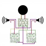
looking at the two diagrams in post1, I can see the speaker Returns are connected to the 3 terminal Ground on the PSU.
This makes this 3 terminal output, the Main Audio Ground (MAG).
All parts of the circuit that need a ground referenced voltage MUST be connected to this same terminal.
Alternatively:
Move the speaker returns from the PSU board and thus MOVE the MAG to a more conventient location that better suits all the twisted cable pairs that are omitted from the diagrams.
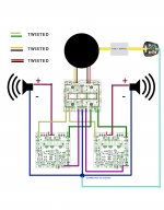
Every connection from Source to Receiver is a cable pair. For best interference attenuation each of these cable pairs should be twisted or coax. I don't like coax for internal wiring. I use twisted pairs everywhere (except when it's a twisted triplet).
Here are two examples:
the transformer has two wires connecting to the PSU board (it actually has two pairs).
The Transformer is the Source, The PSU is the Receiver.
Connect the Source to the Receiver with a twisted pair, repeat for the other two wires.
The speaker is connected to the amplifier with two wires.
The amplifier is the Source the speaker is the Receiver.
Connect the amplifier to the speaker with a twisted pair.
This DEMANDS that the speaker return wire must go back to the amplifier, NOT to the PSU.
This makes this 3 terminal output, the Main Audio Ground (MAG).
All parts of the circuit that need a ground referenced voltage MUST be connected to this same terminal.
Alternatively:
Move the speaker returns from the PSU board and thus MOVE the MAG to a more conventient location that better suits all the twisted cable pairs that are omitted from the diagrams.
Every connection from Source to Receiver is a cable pair. For best interference attenuation each of these cable pairs should be twisted or coax. I don't like coax for internal wiring. I use twisted pairs everywhere (except when it's a twisted triplet).
Here are two examples:
the transformer has two wires connecting to the PSU board (it actually has two pairs).
The Transformer is the Source, The PSU is the Receiver.
Connect the Source to the Receiver with a twisted pair, repeat for the other two wires.
The speaker is connected to the amplifier with two wires.
The amplifier is the Source the speaker is the Receiver.
Connect the amplifier to the speaker with a twisted pair.
This DEMANDS that the speaker return wire must go back to the amplifier, NOT to the PSU.
Last edited:
No.
The Mains PE wire must be permanently and mechanically fixed to the Chassis.
It should NOT be taken to the MAG.
You have separated the speaker return wire from the speaker flow wire. twisted pair.
The PSU to Amp triplet (+, -, 0) must also be twisted. You have omitted the 0 wire from your legend.
The Mains PE wire must be permanently and mechanically fixed to the Chassis.
It should NOT be taken to the MAG.
You have separated the speaker return wire from the speaker flow wire. twisted pair.
The PSU to Amp triplet (+, -, 0) must also be twisted. You have omitted the 0 wire from your legend.
Hi guys so I have built my MX 50 SE it sounds okay but I feel like it is not getting enough power when I turn the volume up it distorts horribly at a lower volume it sounds okay I am supplying it with 36 V DC my question is do I need to supply it with more voltage to get a cleaner sound or is there something else wrong both channels sound the same thank you in advance for any input
Does anyone know were I need to attack my 3mm aux cord to get sound from my phone to go through the board ?
Getting music in
Does anyone know how to actually get music from my phone to go through the board and to the speaker. Where do I plug my aux in
Does anyone know how to actually get music from my phone to go through the board and to the speaker. Where do I plug my aux in
If you already wired RCAs (and they are working properly), just buy a 3.5mm to RCA adapter cable. Plug 3.5mm jack into phone, and RCAs into your amplifier.
If no RCA's, then you will wire up a female 3.5mm chassis connector and wire it to the input blocks of you amp board. Then plug in 3.5mm plug from phone to amp.
Set volume low on phone and turn on amplifier. Then slowly turn up phone volume until you get music. DONE#
If no RCA's, then you will wire up a female 3.5mm chassis connector and wire it to the input blocks of you amp board. Then plug in 3.5mm plug from phone to amp.
Set volume low on phone and turn on amplifier. Then slowly turn up phone volume until you get music. DONE#
- Home
- Amplifiers
- Solid State
- LJM MX50SE - Wiring and Ground?