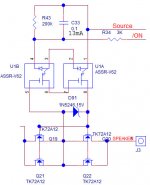
Attached is the speaker protection part of my design. My question is whether I should put a 10M resistor across D91 to breed off the voltage when the input LED is off. I just afraid if there is no resistor, the capacitance of the gate of the transistors will hold the voltage and keep the FET on for a long time. And it will defeat the speaker protection.
I also attached the datasheet of Avago FET driver.
Thanks
I also attached the datasheet of Avago FET driver.
Thanks
Attachments
I think you are missing the current drain that allows the FETs to switch to OFF/OPEN
The current from the LEDs drives the FETs to ON/CLOSED
This is fast part of the switching.
The slower part is the going to OFF when there is a need to isolate the speakers.
I see "turn off circuit" integrated in the FET driver. This is responsible for the fast turn off, so I would not use any other parts for it.
Sajti
I saw the "turn off circuit". But what does that mean? It specified turn off time, BUT it specified at 10mA and CL=1nF. Is CL the gate source capacitance of the MOSFET it is driving? It really does not explain anything. that's why I post this.
I hope someone actually used this part can join in.
I hope someone actually used this part can join in.
I saw the "turn off circuit". But what does that mean? It specified turn off time, BUT it specified at 10mA and CL=1nF. Is CL the gate source capacitance of the MOSFET it is driving? It really does not explain anything. that's why I post this.
I hope someone actually used this part can join in.
Hi,
the specified turn off time is turn OFF with 1nF load (MOSFET input capacitance), and turn OFF from 10mA led current.
Sajti
ThanksHi,
the specified turn off time is turn OFF with 1nF load (MOSFET input capacitance), and turn OFF from 10mA led current.
Sajti
Then I don't have to put the resistor across the D91 to help collapsing the voltage then.
Good.
Thanks
Have you read any of the Threads discussing this?I saw the "turn off circuit". But what does that mean? It specified turn off time, BUT it specified at 10mA and CL=1nF. Is CL the gate source capacitance of the MOSFET it is driving? It really does not explain anything. that's why I post this.
I hope someone actually used this part can join in.
Have you read Bonzai's PDF on this topic?
If you leave the gate charged up, then the mosFET will never turn off. Your SS relay will turn ON and once on will never turn off.Thanks
Then I don't have to put the resistor across the D91 to help collapsing the voltage then.
Good.
Thanks
You NEED to turn it OFF to make the SS relay effective.
The Turn OFF should be quick, nut it usually ends up being a bit slower than the Turn ON.
The time it is turning ON, or turning OFF, times the current that is flowing is the effective energy building heat inside the device.
Slow turn ON, or OFF, leads to excessive heating.
I read 30 pages of this thread:http://www.diyaudio.com/forums/solid-state/191449-output-relays-28.html
The V621 has a turn off circuit and Mooly in post #277 shows the turn off time of 400uS without additional resistor. I doubt adding a 4.7M will speed up any at all. Looks like the V621 take care of the turn off time.
The V621 has a turn off circuit and Mooly in post #277 shows the turn off time of 400uS without additional resistor. I doubt adding a 4.7M will speed up any at all. Looks like the V621 take care of the turn off time.
Yes, I am still talking about the schematic in post 1 of this thread. I am referring to post #277 of the thread I linked that Mooly tested with two of the V621 output in series and showed 400uS turn off time with no resistor helping to pull charge out of the gate of the MOSFET.
You seems to say the V621 need help to turn off the FET, from Mooly's scope picture, it turned off just fine.
You seems to say the V621 need help to turn off the FET, from Mooly's scope picture, it turned off just fine.
looking for post277
Is V621 similar to V62?
the SS relay is not detailed.
look at post288
R5 discharges the gate.
Some have R5 getting lower than 10k
post6 & post9.
Read Bonzai.
http://hifisonix.com/solid-state-relay-with-pcb-layout/
Is V621 similar to V62?
the SS relay is not detailed.
look at post288
R5 discharges the gate.
Some have R5 getting lower than 10k
post6 & post9.
Read Bonzai.
http://hifisonix.com/solid-state-relay-with-pcb-layout/
Last edited:
looking for post277
Is V621 similar to V62?
the SS relay is not detailed.
look at post288
R5 discharges the gate.
Some have R5 getting lower than 10k
post6 & post9.
Read Bonzai.
Solid State Relay with PCB Layout
The V621 and V622 modules are complete ready made driver modules. They take care of discharging the output voltage themselves. I use these same modules in my speaker relays too. It's been a while since I measured operation and my test equipment is junk so I can't quote any numbers but turn off is instant.
Attached is the speaker protection part of my design. My question is whether I should put a 10M resistor across D91 to breed off the voltage when the input LED is off. I just afraid if there is no resistor, the capacitance of the gate of the transistors will hold the voltage and keep the FET on for a long time. And it will defeat the speaker protection.
I also attached the datasheet of Avago FET driver.
Thanks
I use almost the same design in my speaker relays. I found I needed to parallel the outputs of the V621 to speed turn on time of the mosfets. I used a single pair of IPB025N-10N3 mosfets for the main switching devices.
I've also done some real world testing on them to make sure they were keeping my speakers safe. I assembled a test amplifier and self destructed it through the relay into a dummy load to see what would happen. The IPB025N-10N3 G will fail soft (blow open). My concern was the mosfets could short on failure.
Another good/bad observation of the Infineon devices is that they fail open circuit quickly. In this application I prefer to have the device fail quickly. In the destruction test my safety circuit had activated and shut everything down but there would have been a few mS of extreme current in that time. I think having these act as a fuse during that time is a good thing. I'd much prefer to replace a mosfet than a speaker. I've used their diodes in some supplies and experienced the same fast failure of devices so I wouldn't recommend their products for that application.
Last edited:
I use almost the same design in my speaker relays. I found I needed to parallel the outputs of the V621 to speed turn on time of the mosfets. I used a single pair of IPB025N-10N3 mosfets for the main switching devices.
I've also done some real world testing on them to make sure they were keeping my speakers safe. I assembled a test amplifier and self destructed it through the relay into a dummy load to see what would happen. The IPB025N-10N3 G will fail soft (blow open). My concern was the mosfets could short on failure.
Another good/bad observation of the Infineon devices is that they fail open circuit quickly. In this application I prefer to have the device fail quickly. In the destruction test my safety circuit had activated and shut everything down but there would have been a few mS of extreme current in that time. I think having these act as a fuse during that time is a good thing. I'd much prefer to replace a mosfet than a speaker. I've used their diodes in some supplies and experienced the same fast failure of devices so I wouldn't recommend their products for that application.
Thanks Jwilhelm
Your information is very helpful. I feel a lot better about the design. I don't worry about turn on time, I only worry about the turn off time if the amp fail with output railed to the power supply voltage. I need to protect the speaker.
You ever try putting the V621 output in series and tested how fast the MOSFET turns off? I read here that V621 turns off fast even in series mode. To me, even if it turns off in 1mS( instead of 400uS), that's plenty fast to protect the speaker already. Remember in crossover network inside the speaker, there is always a big inductor in series with the woofer that prevent the current to spiking up that fast.
In the destruction test, do you just short the output of the amp and see how the MOSFET fail? Seems to me the usual protection rail fuse should blow before the MOSFET. I have fuse for both rails on the pcb, I would expect the fuse to blow way before the MOSFET burn.
I use the Toshiba TK72A12N1, it has 4.5mohm RDSON, I don't know how it would fail.
Thanks
looking for post277
Is V621 similar to V62?
the SS relay is not detailed.
look at post288
R5 discharges the gate.
Some have R5 getting lower than 10k
post6 & post9.
Read Bonzai.
Solid State Relay with PCB Layout
I really don't want to get so fancy that I have to put in a whole circuit like that. from everything I read, the V621 will do just fine even using in two with output connected in series. Turning off in 400uS is plenty fast. So if it is 1mS, so what?
I am going to add a 2M or a 4.7M resistor in parallel with the D91. It is about 10mS time constant, but it's a good insurance anyway. I don't think it is required to turn off any faster as the woofer always have a big inductor in series that prevent the current from spiking too fast.
You should worry about turn on time as well. If the mosfets don't fully turn on fairly quickly they will make heat and possibly incomplete turn on,which will snowball and make more heat and poor sound.Thanks Jwilhelm
Your information is very helpful. I feel a lot better about the design. I don't worry about turn on time, I only worry about the turn off time if the amp fail with output railed to the power supply voltage. I need to protect the speaker.
You ever try putting the V621 output in series and tested how fast the MOSFET turns off? I read here that V621 turns off fast even in series mode. To me, even if it turns off in 1mS( instead of 400uS), that's plenty fast to protect the speaker already. Remember in crossover network inside the speaker, there is always a big inductor in series with the woofer that prevent the current to spiking up that fast.
In the destruction test, do you just short the output of the amp and see how the MOSFET fail? Seems to me the usual protection rail fuse should blow before the MOSFET. I have fuse for both rails on the pcb, I would expect the fuse to blow way before the MOSFET burn.
I use the Toshiba TK72A12N1, it has 4.5mohm RDSON, I don't know how it would fail.
Thanks
For my destruction test I had a Slewmaster input board that was oscillating, so I put some slow drivers on a test output board and fired it up with 75V rails. I figured an out of control high power amplifier would be about the worst possible scenario for a speaker protection system so I should test with that in a controlled fireproof environment and a fire extinguisher handy.
Semiconductors are much faster than fuses. The 12 amp rail fuses weren't blown in my test if I recall correctly. You can do a lot of damage before a rail fuse lets go.
But even without any help, the FET will turn on within 1mS by the V621.
I don't believe it will partially turn on. I work with MOSFET for years, you need the initial few uS to turn on really hard by driving to +15V at the gate. BUT after that it only takes a few volts to keep it hard on. It will never be partially on if you have gate source at 10V. It is hard on. If you look at the spec of your transistor, even at 6V, it's down to 4.4mohm max. This is hard on.
Isn't 15A fuse a little high? I use 4 to 6A fuse and I still use two MOSFET pair in parallel. My guess it's the bonding wires inside that pop open, those wires are small. that's the reason I start with two parallel pairs.
Another question is whether I need diode protection after the SS relay one to each rail to drain out the inductor kick from the speaker when the SS relay turns off as it turns off so fast. The body diode is not going to do that.
Last edited:
But even without any help, the FET will turn on within 1mS by the V621.
I don't believe it will partially turn on. I work with MOSFET for years, you need the initial few uS to turn on really hard by driving to +15V at the gate. BUT after than it only takes a few volts to keep it hard on. It will never be partially on if you have gate source at 7V. It is hard on.
Isn't 15A fuse a little high? I use 4 to 6A fuse and I still use two MOSFET pair in parallel.
75V rails into 4 ohms creates quite a bit of current. If you look closely at your rail fuses after a hard test run and see a little discoloration in the middle of the element, the fuse is too small. It looks very similar to crossover distortion on a scope. The fuse will begin to melt on the peaks of a sine wave.
I use rail fuses pretty much for fire protection and use my protection circuits for actual component protection. I'm in the process of adding shut down mosfets in the rails at my supply. No more waiting for supply caps to finish unloading into an overheated output device before it stops.
Last edited:
Ha ha, I guess we are talking about apple and orange. I run high bias current of 200mA per stage and I use 5 stages to give 1A idle current. BUT I run my first test amp at +/-25V using a switching supply. My real one is going to be +/-40V. I am gunning for 10W of Class A and move to class AB at higher power. For myself, I really only need 2W or so at home, the rest are just overhead for quick transient signal.75V rails into 4 ohms creates quite a bit of current. If you look closely at your rail fuses after a hard test run and see a little discoloration in the middle of the element, the fuse is too small. It looks very similar to crossover distortion on a scope. The fuse will begin to melt on the peaks of a sine wave.
I use rail fuses pretty much for fire protection and use my protection circuits for actual component protection. I'm in the process of adding shut down mosfets in the rails at my supply. No more waiting for supply caps to finish unloading into an overheated output device before it stops.
I don't see rail fuse will introduce distortion to the output. I can see if you have a fuse is series with the speaker, that is distortion big time. rail fuse only for power supply.
Last edited:
- Status
- Not open for further replies.
- Home
- Amplifiers
- Solid State
- question on speaker protection circuit