Hi Colin,
Are you offering these for sale? It appears that you might be.
We do have a commercial section on this site where you can "set up shop". We generally do not allow this activity in the general forums.
If you are all about the design rather than the sale, you can certainly start a thread where the design can be discussed and built by other members. In this case you must disclose the schematic, parts and any important details (like component matching for example). You must also post the PCB layouts. You are then welcome to sell PCBs and kits to our members who choose to go that route.
-Chris
All the information is now being published on.
one4audio ? The S.E.C.A amps kits – the building process as experienced by a novice builder | HiFi Answers
This is part 2 I have to write up more ASAP has Howard needs to complete the article, so I need nagging with all the other things I am doing I have a system overload.
Also the bigger brother is being made by James on
Sovereign's New 40W SECA Class A - Audio Chews
This will be the first one made so I will be watching with interest.
Hi Root2,
You would need to disclose the entire schematic and info in the thread. You are pretty much a vendor, so it's a gray area. As a vendor, you could make PCBs and parts kits available for sale but always allow those who can to build the entire thing from scratch. This is audio DIY after all.
If you have a number of products you should really be in a commercial area of the site. There is latitude here.
I'll go ask.
-Chris
So these are kits to buy?
No but I do have PCB's to sell, but not complete kits.
Parts will depend on what Radio Shack and others have to match the required components. And since this is now available all over the world we all do not have Maplins etc.
")
Best Colin Wonfor
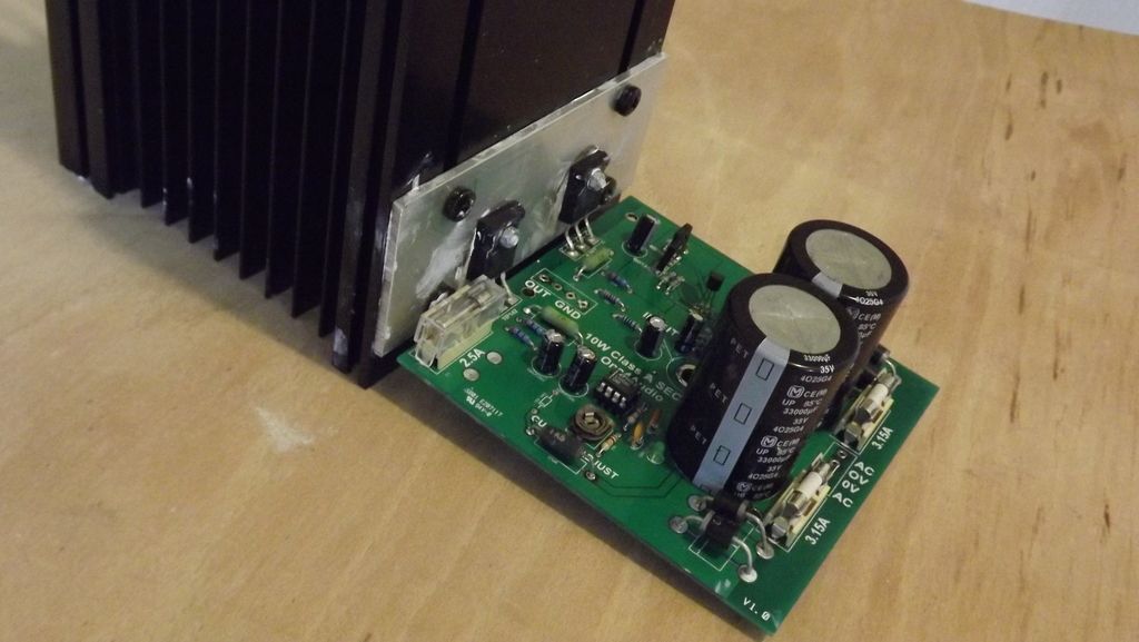
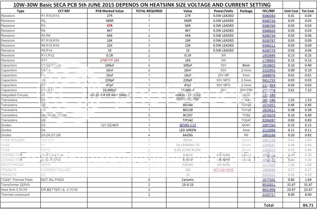
I have also tried large FET's in place of the TIP142 but use a low RDsON type with a large gate capacitance , this will improve stability. As some FET went into self oscillation.
Also tried 55A 600V IGBT they also work but the loses across them was very high in the order of 2.5 - 3.2V where the TIP142 was 1.4V and the FET was below 100mV in full saturation.
The heatsink I used were 2 of AAVID THERMALLOY D180-20 HEAT SINK, T SLOTS, 0.33°C/W one for each channel.
Also tried 55A 600V IGBT they also work but the loses across them was very high in the order of 2.5 - 3.2V where the TIP142 was 1.4V and the FET was below 100mV in full saturation.
The heatsink I used were 2 of AAVID THERMALLOY D180-20 HEAT SINK, T SLOTS, 0.33°C/W one for each channel.
An externally hosted image should be here but it was not working when we last tested it.
Hi Colin,
That's quite a tidy board/heatsink arrangement for class A. I'm curious though to know of any distinct differences in sound quality, apart from the important stability issues, between the various output device combinations you tried. Could you share any further thoughts on this?
That's quite a tidy board/heatsink arrangement for class A. I'm curious though to know of any distinct differences in sound quality, apart from the important stability issues, between the various output device combinations you tried. Could you share any further thoughts on this?
Last edited:
Hi Ian,
They are sound rich powerful in control and I have a few review on other I have designed as completed units for Inca Tech, Magnum,TOCA, and Tellurium Q, the reviews are out in the Interweb somewhere.
And asking me is not good I am very biased to my own creations, ask others.
Best Col
They are sound rich powerful in control and I have a few review on other I have designed as completed units for Inca Tech, Magnum,TOCA, and Tellurium Q, the reviews are out in the Interweb somewhere.
And asking me is not good I am very biased to my own creations, ask others.
Best Col
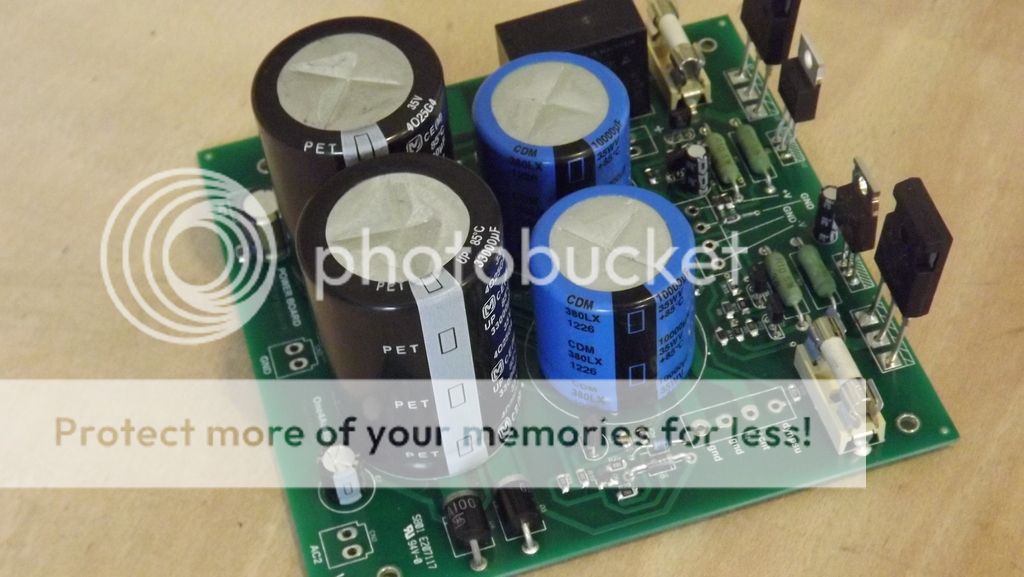
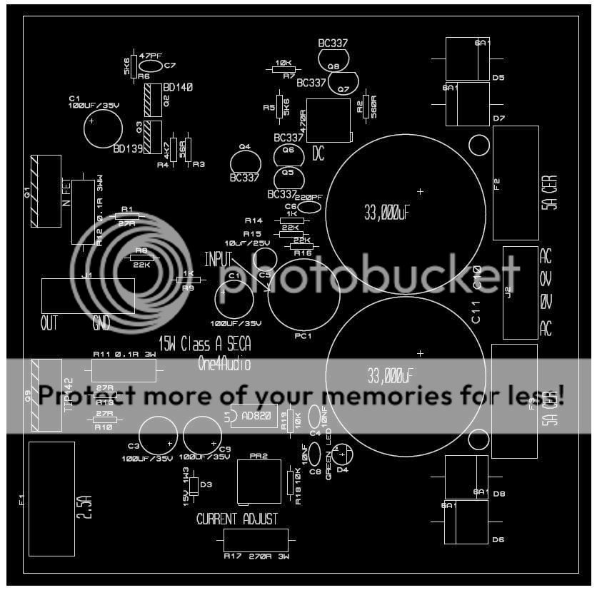
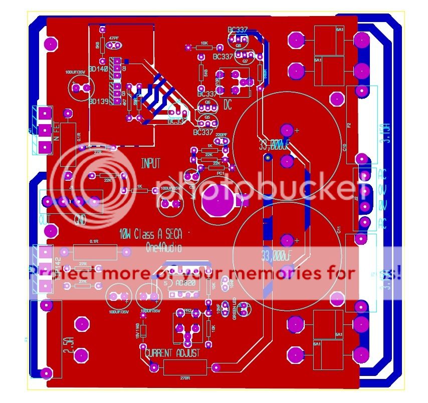
SECA super version
Now working on a super version will be available in a few month after I have tried to kill it. It will out perform the Iridium but it will not be so cheap to make as the baby version now available, parts are silly prices (sorry). It will use the same PSU but will also self generate on the Amp PCB a 2 x Vc drive this will push the dynamics higher and increase the bandwidth to a silly 1MHz, we do filter the input to stop you local Taxi service from wrecking the sound but the amp damping factor will also improve.
And from those out there who commented on the less expensive Amp thanks for your input on construction it has all been implemented. See Pic.
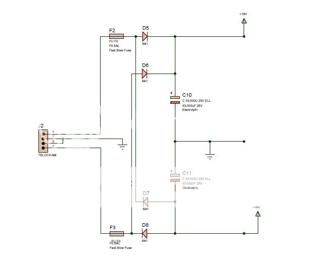
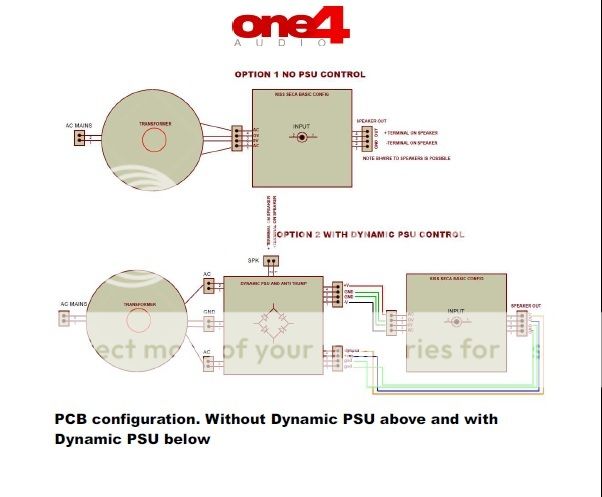
Here is how to connect the Dynamic PSU to either SECA PCB.
Hi Colin,
What is the "Dynamic PSU" all about?
-Chris
Hi Chris,
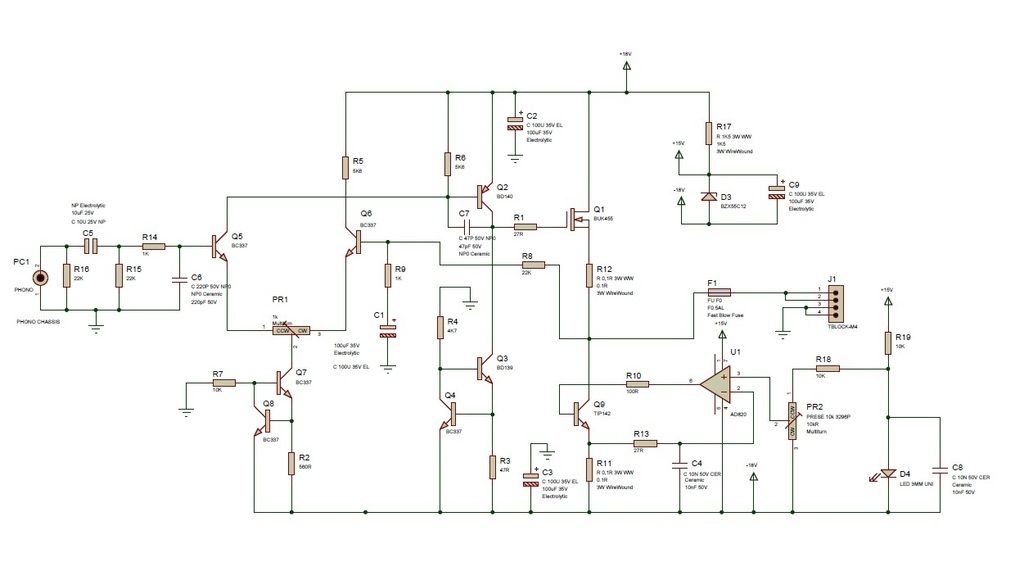
Under normal low power operations and before the amp clips. The output of the amp is fed into the reference of the PSU, this will allow the PSU to track the output, i.e when going positive the +V rail goes up but the -V goes down this reduce the Pd in either the FET (the main Amp) or the Darlington (constant current) reducing the heat on these devices. This happens in reverse also when the output goes negative +V down,-V up or more negative.
Oh I forgot the ripple on the amp output is normally highish with SECA designs so we use huge caps in the PSU, but with this PSU it only 5mV or less with relatively small caps.
Now here is the rub to keep up with the amp the PSU has to dump current at very high speed, but with large caps, how??? And with current shutdown/foldback.
Col
Last edited:
Hi Colin,
I would suggest you study the fine work that Bob Carver had done over the course of many years. Something along the lines of a TFM-55x, or even a TFM-45 would probably show you what you needed to know.
His designs were often three tier designs that used an active mid tier such as you describe, then a bang-bang top tier supply. Some earlier designs tracked the output with both the higher tiers. He found out early on that when a higher supply voltage kicks in suddenly with high dv/dt, the leading edges would ride through the output transistors. This caused the amplifier to sound harsh. Not the effect he was going for.
It is important that the supply holds up for a short time after the output begins to fall, but that creates another issue. If the amp is only fed higher frequencies the supplies would "lock up", exposing the output stage to the full supply voltage - +&- 125 VDC. I kid you not! In this condition the amplifier would enter thermal runaway.
The second massive improvement he created was with the raw supply voltage. He used a "mag coil" that could output voltages far in excess of the supply capacitors voltage ratings. This gave him the opportunity to regulate the "raw" power supply voltages. So, for lower AC line conditions the amp would draw a little more current, for higher AC the reverse was true. The problem with that was some folks liked to run big amplifiers off of extension cords or worse, little gas generators! Some technicians figured the triac was a power switch, so they would sometimes short it (!!!!!) and plug it in. If they blew the bench circuit breaker, they were lucky.
These are very reliable and time tested designs. If you looked over his work from the M-400 (cube) amplifier up to the TFM-55x you would see the changes he made over time, and probably the reasoning for those changes. More importantly you can see how he divided the supply voltages as they were based on music.
His later designs (Lightstar) used +&- 125 VDC rail voltages and a "down converter" which would track the music waveform. The range of adjustment ran about 13 VDC up to the enormously powerful 110 VDC. I never got that amp higher as it tripped the 15A industrial breaker in my shop for my bench. Just stupid amounts of power.
Anyway, I think that Bob Carver has your answers, and you have the advantage of coming in late on his research. You don't have to learn the same lessons. I think that in Europe, some of his product may have been called "Bennytone". I have seen his M-500 in gold-ish colour with those two giant meters. One of the more pretty amplifiers that came from Carver. The same amp over here was gray.
-Chris
Hi Colin,
I would suggest you study the fine work that Bob Carver had done over the course of many years. Something along the lines of a TFM-55x, or even a TFM-45 would probably show you what you needed to know.
His designs were often three tier designs that used an active mid tier such as you describe, then a bang-bang top tier supply. Some earlier designs tracked the output with both the higher tiers. He found out early on that when a higher supply voltage kicks in suddenly with high dv/dt, the leading edges would ride through the output transistors. This caused the amplifier to sound harsh. Not the effect he was going for.
It is important that the supply holds up for a short time after the output begins to fall, but that creates another issue. If the amp is only fed higher frequencies the supplies would "lock up", exposing the output stage to the full supply voltage - +&- 125 VDC. I kid you not! In this condition the amplifier would enter thermal runaway.
The second massive improvement he created was with the raw supply voltage. He used a "mag coil" that could output voltages far in excess of the supply capacitors voltage ratings. This gave him the opportunity to regulate the "raw" power supply voltages. So, for lower AC line conditions the amp would draw a little more current, for higher AC the reverse was true. The problem with that was some folks liked to run big amplifiers off of extension cords or worse, little gas generators! Some technicians figured the triac was a power switch, so they would sometimes short it (!!!!!) and plug it in. If they blew the bench circuit breaker, they were lucky.
These are very reliable and time tested designs. If you looked over his work from the M-400 (cube) amplifier up to the TFM-55x you would see the changes he made over time, and probably the reasoning for those changes. More importantly you can see how he divided the supply voltages as they were based on music.
His later designs (Lightstar) used +&- 125 VDC rail voltages and a "down converter" which would track the music waveform. The range of adjustment ran about 13 VDC up to the enormously powerful 110 VDC. I never got that amp higher as it tripped the 15A industrial breaker in my shop for my bench. Just stupid amounts of power.
Anyway, I think that Bob Carver has your answers, and you have the advantage of coming in late on his research. You don't have to learn the same lessons. I think that in Europe, some of his product may have been called "Bennytone". I have seen his M-500 in gold-ish colour with those two giant meters. One of the more pretty amplifiers that came from Carver. The same amp over here was gray.
-Chris
Hi Chris,
I do not wish to be rude, but I have been designing large PSU,s for many years, some are huge 100KA @ 55V linear type to 150KVA resonant high voltage 150KV and a few for NASA , many for military equipment.
I have also been designing audio and hifi for over 50yrs.
I started life in my career as a chemist I hated it my hobby was electronics so after I graduated I went back to Uni to study Electronics, then at 50 I went on to Scotland and studied computer science I hated it.
My Grandad and Dad were both electronic engineers so it is in my blood.
I have seen Mr Carvers work it is good but it is not my way I like K.I.S.S. Keep It Simple Stupid, for me it works I found talking to non techy managers a pain so I would always present it in a K.I.S.S. they never understood the maths anyhow.
So I have studied for a while now and understood the operational aspects and speed that I need to follow the output stage with and lock up does not happen and the other is dI/dT can be solved by using the right part.
Back soon
Steve on Sunday was forced to listen to this he he.
"DIY SECA Kit
I recently had the opportunity to hear the best sounding 'computer case' I've come across..!
I'm not a reviewer so bear with me if my analogies are a bit wayward, but I'm trying to find ways to express a 'sense' through words. I should add that the time spent was more of a listen than a test or review and connected components were only a 10+ year old DVD player as source (!), bog standard IEC power cables and cheap mid-sized stand-mount speakers. I'll surmise my thoughts based on existing experience (neither vast nor exotic) - They're musical, fast, detailed, pure and textured.
From cold, the opening track through the SECAs began with a thrum across acoustic guitar that was open with an in-the-room'ness quality…
With acoustic, ambient/electronic and voice the overriding sense is that the SECAs are VERY open, detailed and light of touch, music seems almost as if carried on air.
The sound is just 'there' and 'pure' rather than other amps that seem to almost push music down a tube, constraining and colouring it. I think the SECAs may be what some would call 'natural' sounding (ie. they don't really add anything).
Sound no longer came from (within) the speakers but more like a bloom of sound that surrounded or escaped their confines and filled the space around with an effortless delivery."
Thanks Steve.
- Status
- This old topic is closed. If you want to reopen this topic, contact a moderator using the "Report Post" button.
- Home
- Amplifiers
- Solid State
- SECA Kit By Colin Wonfor