Hi Colin,
Well, the fact remains that Mr. Carver did execute what you are looking at a number of years ago, and his concepts worked very well along with being a commercial success. My advice was tempered by the knowledge that many sell Bob short when they shouldn't. Given that you were investigating doing the same thing, I figured you had come across Bob's work and had dismissed it.
The work I had suggested you look at was a two part deal. One, the tier switching (which he solved nicely) is well worth your consideration. Solving a technical problem is best done by design, not just with special parts as you well know. His execution of the tiered voltage switching is not complicated and addressed your stated problem directly, so why wouldn't it have value to examine? In addition, I tried to bring your attention to an alternative method of controlling Vce in the output stage, since that is the later direction Bob took. It gives you options and other viewpoints to consider.
The second part of his work involved the regulation of the internal voltages at the earliest point where power meets circuit. This is an increase in efficiency, which is the direction I thought you were heading in. Therefore, that segment of his work was included in the "recommended reading".
I wasn't aware of your professional history, but I was attempting to be helpful. Directing you to Bob's work was the most helpful thing I could do. Of course my history is likely a mystery to you, and that's fine. I'll just say that my involvement in audio electronics on a technical and professional level has spanned over 35 years now. I did consider what you needed before replying to you.
Sometimes KISS is too simple. You might not like Mr. Carver, but his approach was generally not complicated. The only parts in his designs are required for either technical or legal reasons. The simpler designs (M-400 cube) did have problems that were cured with the later designs.
Having studied Bob Carver's designs, I would be interested to see how you deal with the same problems, and also what you consider to be too complicated in his design. I am genuinely interested in your approach, please don't take my posts as anything beyond an honest attempt to help mixed with curiosity. If you read more into them, I apologize because that was not my intent.
-Chris
Thanks Chris,
I have and will again look at Bob's work as there is nothing wrong with his approach or mine.
Thanks again.
I have and will again look at Bob's work as there is nothing wrong with his approach or mine.
Thanks again.
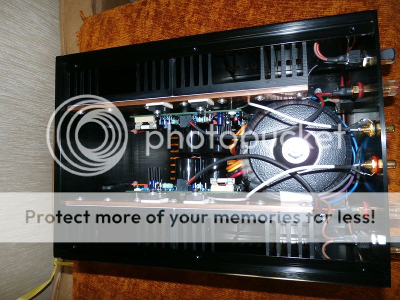
There is certainly every assistance to heat transfer with that thick copper(?) strap. It's a pity though, that the power transistors had to be mounted to the top edge of the sinks which I guess was necessary if they they had to be split in 2 pieces that way.
As those small Chinese cases can be purchased cheaply with the whole sides being heatsinks, it will be my next project to build a 12W class A amplifier with similar sized PCB but with the boards rotated 90° to align the transistors closest to the front or rear, to place the input stage furthest from the transformer which I have to say, is virtually touching the PCBs here. Similarly, the transformer leads could be better located but perhaps the finishing touches haven't been made yet.
Class A amplifiers are a pain to rid of hum. What works fine on the bench or breadboard suddenly produces nagging hums, buzzes, and mechanical transformer noises when you jam it in box and call it finished. We may tolerate it but the whole point of class A is noise free, super-clear reproduction and this takes more than a few tricks of layout and lead dress before there are audible improvements. If achieved, we can be deservedly proud of the device and enthusiastic to keep using it for any low power application from headphones to sensitive full range floorstanders.
Hi Colin,
That is a really clean build. Wonderful. So, how does it sound?
The only thing I would do is have more length on your input leads. They are too tight.
-Chris
That is a really clean build. Wonderful. So, how does it sound?
The only thing I would do is have more length on your input leads. They are too tight.
-Chris
Hi Colin,
That is a really clean build. Wonderful. So, how does it sound?
The only thing I would do is have more length on your input leads. They are too tight.
-Chris
Hi Chris, I never made this one Paul Quick did on Audiochews forum, he is very good at construction, and I have been friends with him since Inca Tech Claymore day 1980's .
He has also built some lovely TOCA Replicas.
Nice man to work with great sense of humor.😀
Col
Thank you chaps 🙂
The layout was pretty much dictated by the size of the case, and the heatsinks and transformers I put in there.
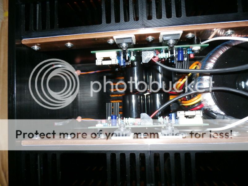
The copper heat spreader works really well, the FET only running a few degrees or so hotter then the sink, and the ends not much cooler.
Sounds wonderfull, silky smooth, but with incredible detail, and decent bass.
Will put some more pics up when I get chance.
Paul.
The layout was pretty much dictated by the size of the case, and the heatsinks and transformers I put in there.
The copper heat spreader works really well, the FET only running a few degrees or so hotter then the sink, and the ends not much cooler.
Sounds wonderfull, silky smooth, but with incredible detail, and decent bass.
Will put some more pics up when I get chance.
Paul.
Hi Paul,
So you're the cook in that kitchen!
You did a really, really nice job on that build. It sounds like that project was well worth while too!
-Chris
So you're the cook in that kitchen!
You did a really, really nice job on that build. It sounds like that project was well worth while too!
-Chris
Thank you chaps 🙂
The layout was pretty much dictated by the size of the case, and the heatsinks and transformers I put in there.
The copper heat spreader works really well, the FET only running a few degrees or so hotter then the sink, and the ends not much cooler.
Sounds wonderfull, silky smooth, but with incredible detail, and decent bass.
Will put some more pics up when I get chance.
Paul.
As a matter of interest Paul, under the ceramic TO247 washers did you use heatsink compound?
Thanks Chris.
Yes, i'm really pleased with the build.
Was a bit of a squeeze geeting it all in there, but worth the effort !
Yes Col, just a fine smear..........you should just be able to see it in the pic.
Yes, i'm really pleased with the build.
Was a bit of a squeeze geeting it all in there, but worth the effort !
Yes Col, just a fine smear..........you should just be able to see it in the pic.

SECA Pre done waiting for PCB (not a kit)
2 off HP
MC
MM
CD
2 off pre-out
No remote and no DAC
100VA PSU
2 off HP
MC
MM
CD
2 off pre-out
No remote and no DAC
100VA PSU
Batch 2 will be here by Thursday.
I have made this batch with a higher density Cu so we can run the driver if required at a high bias this will increase the Bandwidth to over 1MHz.
The circuit has been designed to run current in A Class in the driver stage with a standing current of 10mA but now it can be pushed to 30mA see table.
R set...........I Drive Current....P dis W..............HS Type
68..................9.68.............. 0.174
56.................10.77..............0.193
51.................11.76..............0.212....... .....Heatsinked.....PCB
47.................12.77..............0.230....... .....Heatsinked.....PCB
39.................15.38..............0.277....... .....Heatsinked.....PCB
33.................18.18..............0.327....... .....Heatsinked......Al
27.................22.22..............0.400....... .....Heatsinked......Al
22.................27.27..............0.491....... .....Heatsinked......Al
18.................33.33..............0.600....... .....Heatsinked......Al
How close are these designs to the EWA amplifiers that came later?
I only ask as I recently bought a pair of EWA M50s second-hand - they sound fantastic by the way! - and wanted to have "balanced" input at a later date.
Do they have a differential input? i.e. that I can just run hot and cold from the XLR as the signal pair? I guess there may be some input level differences in doing that, but I can perhaps sort that out at the pre-amp side (it will be a Bruno Putzey BPBBP ).
Can I infer the same information from this design, should I need to work it out for myself?
Thanks!
The latest SECA designs
An externally hosted image should be here but it was not working when we last tested it.
An externally hosted image should be here but it was not working when we last tested it.
An externally hosted image should be here but it was not working when we last tested it.
- Home
- Amplifiers
- Solid State
- SECA Kit By Colin Wonfor