Hi Sam,
I haven't got around to try the Instrumentation Amplifier (INA) setup yet.
But I truly believe that if the problem is a common mains hum field (and there is a good ossibility that it is) - an INA will solve it.
I haven't got around to try the Instrumentation Amplifier (INA) setup yet.
But I truly believe that if the problem is a common mains hum field (and there is a good ossibility that it is) - an INA will solve it.
Hi Per thanks a lot !
From your previous posts I picked up attached 2 mods, should I disregard these ?
what are the types of the additional trannies ?
and the fance double config, is that a special component or a matched pair thermally coupled ?
cheers Dirk
Hi Dirk,
Ah yes, those were the very first stages in the upgrade. They did do a great job in reducing positive rail noise, but I have since found that a perfectly matched LTP input section increases the PSRR sharply, so these mods are not required. They are not 'fancy' - just standard cascode and current source sharing stuff.
I use KSA992 and KSC1845 in the VAS module, BCM847DS in the current mirror.
Per
Hi Sam,
I haven't got around to try the Instrumentation Amplifier (INA) setup yet.
Hi Per,
Where exactly in Rotel or Asus Xonar?
Hello everyone,
thanks for the great Information in this thread, especially AngelP/Per for his thoughtfull advices and sharing his experience! I read not all, but much of it.
I just bought a Rotel RA-970BX for a good price which is now shipping to me.
I want to apply a few mods whithout that much effort, as I'm more the speaker guy and several projects waiting for me...
First of all, when it arrives I will do initial function check and visual inspection of the inside, clean potentiometers and switches, check capcaity of main capacitors and also measure DC offset and bias voltage (and adjust it, if necessary).
The following I have more or less decided:
This should be easy to do and costs are only a few Euros.
But after reading here I got more motivated to do further little modifications, but I fear to damage something by making the amplifier worse or unstable, so I have some questions hoping for advice.
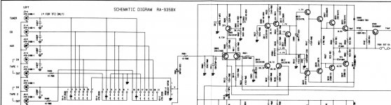
I had some lectures on Electronics during my studies but that is long time ago, and I'm able to "read" the amplifier architecture from the schematics as differential input stage, VAS stage, drivers, output stage, local feedback resistors, current mirror, e.g. but no further experience with analyzing/calculating overall stability and such topics.
I also have no special equipment as my multimeter and a good regulated soldering iron, so checking with oscilloscope or measuring and matching transistors is no option. Due to this I'm dependent on "plug and play" solutions which limit the risk of damage to my soldering skills...
My ideas/questions:
1) There is advice for other Rotel amplifiers to decrease C609 from 330pF to much lower 27pF and leave R629 33k completely out. Can it be done without further risk or modifications?
2) There was also discussion to completely get rid of C613/C615 to decrease capacitive load of the VAS stage, but others said that this may lead to local oscillations of the output stage. At the moment I tend to better leave them in. (BTW: right next to the caps there is a shortcut in the schematics, hope that this is just a mistake - or to fool copycats without knowledge...)
3) Adding 68pf miller capacitors to VAS Q613/Q615 transistors; can I just do that and it "improves" (from "Rotel" to more "HiFi" sound), or are further analysis/modifications needed?
4) 1,5k R605/R607/R609/R611 in the differential output stage: seems sexy and easy to change them for a current mirror pair of transistors (and maybe additional 100 Ohm emitter resistors) which may help to power the VAS stage (and miller caps) better. But I have no idea what parts to choose and if they have to be exactly matched. Do you have a recommendation what to buy (no SMD, wire through preferred) or is this not so easy?

Thanks a lot!
Best regards
Peter
thanks for the great Information in this thread, especially AngelP/Per for his thoughtfull advices and sharing his experience! I read not all, but much of it.
I just bought a Rotel RA-970BX for a good price which is now shipping to me.
I want to apply a few mods whithout that much effort, as I'm more the speaker guy and several projects waiting for me...
First of all, when it arrives I will do initial function check and visual inspection of the inside, clean potentiometers and switches, check capcaity of main capacitors and also measure DC offset and bias voltage (and adjust it, if necessary).
The following I have more or less decided:
- Change the AD827JN Preamp OP for LME49860NA which I found and just ordered here https://www.ebay.de/itm/304157715207 to decrease noise (hope these are not fakes).
- Change all DC decoupling bipolar capacitors in the signal path and feedback loop for Nichicon Muse UES type with 1by1 specification
- Change values of R603/604 from 47k to 22k metal type to improve DC offset as suggested here and in other threads
This should be easy to do and costs are only a few Euros.
But after reading here I got more motivated to do further little modifications, but I fear to damage something by making the amplifier worse or unstable, so I have some questions hoping for advice.
I had some lectures on Electronics during my studies but that is long time ago, and I'm able to "read" the amplifier architecture from the schematics as differential input stage, VAS stage, drivers, output stage, local feedback resistors, current mirror, e.g. but no further experience with analyzing/calculating overall stability and such topics.
I also have no special equipment as my multimeter and a good regulated soldering iron, so checking with oscilloscope or measuring and matching transistors is no option. Due to this I'm dependent on "plug and play" solutions which limit the risk of damage to my soldering skills...
My ideas/questions:
1) There is advice for other Rotel amplifiers to decrease C609 from 330pF to much lower 27pF and leave R629 33k completely out. Can it be done without further risk or modifications?
2) There was also discussion to completely get rid of C613/C615 to decrease capacitive load of the VAS stage, but others said that this may lead to local oscillations of the output stage. At the moment I tend to better leave them in. (BTW: right next to the caps there is a shortcut in the schematics, hope that this is just a mistake - or to fool copycats without knowledge...)
3) Adding 68pf miller capacitors to VAS Q613/Q615 transistors; can I just do that and it "improves" (from "Rotel" to more "HiFi" sound), or are further analysis/modifications needed?
4) 1,5k R605/R607/R609/R611 in the differential output stage: seems sexy and easy to change them for a current mirror pair of transistors (and maybe additional 100 Ohm emitter resistors) which may help to power the VAS stage (and miller caps) better. But I have no idea what parts to choose and if they have to be exactly matched. Do you have a recommendation what to buy (no SMD, wire through preferred) or is this not so easy?
Thanks a lot!
Best regards
Peter
Change the AD827JN Preamp OP for LME49860NA which I found and just ordered here https://www.ebay.de/itm/304157715207 to decrease noise (hope these are not fakes).
And why don't you want to make a shorter path like in 935, as well as replace the volume control from 50 kOhm to 10 kOhm.
Attachments

Mmmh, have to think about that... what may be the disadvantages?
So thank's for the sugesstion, but I will keep the Opamp....
BTW: I once owned an RA-935BX MkII in my youth in the 90s and liked it a lot! A shame that I sold it long time ago....
Best regards
Peter
- The preamp stage adds gain and relieves the power amp stage from that.
- It also avoids the sources to drive the power amp stage directly, better decoupling, more independent from cable properties.
- The power amp is driven by much lower Opamp output impedance, power stage source impedance is independent from position of the volume potentiometer; I'm even thinking of leaving R601 out or reducing the value to drive the power stage more direct.
- Replacing the volume pot to 10k will give even much lower input impedance, and may worsen channel equality due to lowering the adjustment range for same output level.
So thank's for the sugesstion, but I will keep the Opamp....
BTW: I once owned an RA-935BX MkII in my youth in the 90s and liked it a lot! A shame that I sold it long time ago....
Best regards
Peter
Mmmh, have to think about that... what may be the disadvantages?
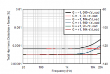
Modern signal sources give out 2 V RMS, and the amplifier input 1 V RMS. The op-amps at the output of the signal source work fine with a 10k ohm load, which essentially provides less noise even with an op-amp at the output of the volume control. The same OPA1656 in the output source as a buffer at the same time provides an output current of 100 mA and extremely low distortion at 10 kOhm and even 2 kOhm.
In my case, replacing 50kOhm with 10kOhm greatly improved Rotel's musicality, and most importantly, the design allows this.
Attachments
Last edited:
At the moment, my signal does not pass through the movable contact of the regulator, but the L-regulator is used, i.e. when the upper resistor of the divider is fixed, and the regulation is carried out by changing the lower resistor of the divider.
The essence of this idea was that the sliding contact of the classic volume control also introduces significant non-linearity and noise, which they tried to avoid. Usually for audiophile equipment in such cases, either expensive discrete (multi-position switch plus a matrix of fixed resistors) regulators (ALPS, DACT), or "non-traditional" inclusion of the regulator are used.
The essence of this idea was that the sliding contact of the classic volume control also introduces significant non-linearity and noise, which they tried to avoid. Usually for audiophile equipment in such cases, either expensive discrete (multi-position switch plus a matrix of fixed resistors) regulators (ALPS, DACT), or "non-traditional" inclusion of the regulator are used.
Hi Per,
Where exactly in Rotel or Asus Xonar?
I was planning to put the INA circuit inside my test box between load resistors and the U7 input.
The U7 input is non-balanced and the INA would make it balanced and effectively eliminate any hum and noise on both sides of the measuring resistor - just picking out the audio signal.
But designing an INA circuit does require quite some cautious pcb layout considerations - also what input and protection components are allowed, etc. It is all too easy to lose a lot (or most) of the optimal CMRR by inconsiderate design.
It will most probably also require a low noise +/-5Vdc supply produced from the noisy +5V USB - or, of course by two 9V PP3 batteries with on/off switches.
😊Never a dull moment in this interesting field - but IMHO more fun than collecting stamps or postcards...... (yes, I did collect stamps in my younger days. If anyone is interested in buying a beautiful collection of Finnish stamps - complete from 1897 to 1997, please send me a message).🙂
Per
The following I have more or less decided:
- Change the AD827JN Preamp OP for LME49860NA which I found and just ordered here https://www.ebay.de/itm/304157715207 to decrease noise (hope these are not fakes).
- Change all DC decoupling bipolar capacitors in the signal path and feedback loop for Nichicon Muse UES type with 1by1 specification
- Change values of R603/604 from 47k to 22k metal type to improve DC offset as suggested here and in other threads
Hi Peter,
The AD827 is a very good opamp, please let us know if you can hear any improvements. Personally, I like the OPA2134.
I increase the 100uF in the feedback path to 220uF - not that a lower frequency roll-off is needed, but it reduces the phase change in the lower bass. And I like the low ESR Panasonic FM types.
My ideas/questions:
1) There is advice for other Rotel amplifiers to decrease C609 from 330pF to much lower 27pF and leave R629 33k completely out. Can it be done without further risk or modifications?
2) There was also discussion to completely get rid of C613/C615 to decrease capacitive load of the VAS stage, but others said that this may lead to local oscillations of the output stage. At the moment I tend to better leave them in. (BTW: right next to the caps there is a shortcut in the schematics, hope that this is just a mistake - or to fool copycats without knowledge...)
3) Adding 68pf miller capacitors to VAS Q613/Q615 transistors; can I just do that and it "improves" (from "Rotel" to more "HiFi" sound), or are further analysis/modifications needed?
4) 1,5k R605/R607/R609/R611 in the differential output stage: seems sexy and easy to change them for a current mirror pair of transistors (and maybe additional 100 Ohm emitter resistors) which may help to power the VAS stage (and miller caps) better. But I have no idea what parts to choose and if they have to be exactly matched. Do you have a recommendation what to buy (no SMD, wire through preferred) or is this not so easy?
!) Yes, that will take away the "pleasing, soft" Rotel sound, but do not remove them without putting in the Miller capacitors! And test without speakers first.
Since you don't have an oscilloscope you will have to rely on AC measurements and checking the component temperatures to detect possible oscillations.
Keep a finger on the off button - and put in lower amp fuses during testing.
2) Leave those caps in for the same reason as above. The short is clearly a drawing mistake.
3) There is a lot of circuit theory and experience going into Miller capacitors. But they do work by kicking in at higher frequencies and reducing gain as to keep the amp stable. Choose them too low and get oscillations - too high in value and your slew rate will suffer. I have seen values ranging from 2pF to 220pF in various amplifiers, I usually keep to the value that Doug Self recommends - 100pF. In your case that means 47pF around the C-B of each of the two VAS transistors if you want to keep the schematic looking nice and balanced. (100pF at just one of the VASs would do as well).
4) No, this is not easy. I will start the posts (I promise!) on my experiences on doing just that on the RA-971 which will cover the challenges.
Best,
Per
It will most probably also require a low noise +/-5Vdc supply produced from the noisy +5V USB
I think it is not necessary to save on voltage (5V), and make it more.
I increase the 100uF in the feedback path to 220uF - not that a lower frequency roll-off is needed, but it reduces the phase change in the lower bass. And I like the low ESR Panasonic FM types.
I installed a non-polar BG NX470x6.3 and the result is very noticeable. A polar capacitor on weak signals has losses caused by the polarization of the dielectric layer and significant (for weak signals ) distortion (i.e., essentially incorrect information).
Hi Per,
thanks a lot for your advices!
I will report how the LME49860NA sounds in comparison. The AD827 has good specs, but lacks noise and I'm sensitive to that.
Do your hear improvements by increasing the value of the feedback path capacitor?
Okay, so I will leave the 220pf VAS capacitors in and the current mirror idea out due to limited experience and measurement equipment...
At first I will listen to the amp, and when i find that it is bit too soft for me I'll try 1) & 2) !
Thanks again and best regards
Peter
thanks a lot for your advices!
The AD827 is a very good opamp, please let us know if you can hear any improvements. Personally, I like the OPA2134.
I increase the 100uF in the feedback path to 220uF - not that a lower frequency roll-off is needed, but it reduces the phase change in the lower bass. And I like the low ESR Panasonic FM types.
I will report how the LME49860NA sounds in comparison. The AD827 has good specs, but lacks noise and I'm sensitive to that.
Do your hear improvements by increasing the value of the feedback path capacitor?
!) Yes, that will take away the "pleasing, soft" Rotel sound, but do not remove them without putting in the Miller capacitors! And test without speakers first.
Since you don't have an oscilloscope you will have to rely on AC measurements and checking the component temperatures to detect possible oscillations.
Keep a finger on the off button - and put in lower amp fuses during testing.
2) Leave those caps in for the same reason as above. The short is clearly a drawing mistake.
3) There is a lot of circuit theory and experience going into Miller capacitors. But they do work by kicking in at higher frequencies and reducing gain as to keep the amp stable. Choose them too low and get oscillations - too high in value and your slew rate will suffer. I have seen values ranging from 2pF to 220pF in various amplifiers, I usually keep to the value that Doug Self recommends - 100pF. In your case that means 47pF around the C-B of each of the two VAS transistors if you want to keep the schematic looking nice and balanced. (100pF at just one of the VASs would do as well).
4) No, this is not easy. I will start the posts (I promise!) on my experiences on doing just that on the RA-971 which will cover the challenges.
Best,
Per
Okay, so I will leave the 220pf VAS capacitors in and the current mirror idea out due to limited experience and measurement equipment...
At first I will listen to the amp, and when i find that it is bit too soft for me I'll try 1) & 2) !
Thanks again and best regards
Peter
Hi everyone,
sorry for my rookie questions, but now I've started to read a bit through Douglas Self - Audio Power Amplifier Design Handbook.
I found this:

Rotel is using option a):

At my - very limited - view it seems like there is some potential to optimise balancing of the differential amplifier just by leaving out R3 respectively R612 and Re-dimensioning of R2 / R618 ?
But the Rotel input circuit has much lower impedance (1,5k vs. 10k) so the imbalance may be much smaller as the current over the restistors vs. to the base of VAS transistor is higher than in Self's circuit...
sorry for my rookie questions, but now I've started to read a bit through Douglas Self - Audio Power Amplifier Design Handbook.
I found this:
Rotel is using option a):
At my - very limited - view it seems like there is some potential to optimise balancing of the differential amplifier just by leaving out R3 respectively R612 and Re-dimensioning of R2 / R618 ?
But the Rotel input circuit has much lower impedance (1,5k vs. 10k) so the imbalance may be much smaller as the current over the restistors vs. to the base of VAS transistor is higher than in Self's circuit...
Hi Peter,
The goal is to send the same DC current through each of the input transistors to balance them, thus lowering distortion and output offset.
a) has a much too big R2 collector resistor, as the voltage over it is the VAS's Vbe - or 0.7V, hence the 70uA current.
This resistor should be designed so it passes about half of the current source value, here 600uA. Thus 0.7V / 0.0003mA = 2k33 or the nearest std. value 2k2 as in b).
R3 has no function and could/should be omitted - but it looks so nice and "balanced" on the schematic.
c) A current mirror greatly improves the LTP balance and reduces distortion gremlins as Self demonstrates.
BUT, you can't use CM's directly in your Double Differential amp topology because there will be no control over the VAS current - and a transistor blue smoke mayhem will soon follow😢.
Which are the difficulties that I plan to cover when I can finally find the time to start the post series.
Per
Last edited:
Hi Per,
thanks for your response!
I tried to reactivate my rusty electronics knowledge a bit, but the voltage levels documented on the schematics seem to make it easy (even if some values may be a bit erratic...).
Assumption of the diffamp currents:

From my rough calculation its seems that 1,8k instead of 1,5k may give a bit better balance, but the 46,1V I took from the schematic may include that some of the current through R605 goes to the base of VAS stage transistor. So in general, Rotel has made a correct job here with dimensioning the diffamp current balance, not much optimization potential here with the values (of course the current mirror will bring improvements!).
As you mentioned, R607 and R611 have no function so they are redundant. But will it bring any improvement to replace them by 0 Ohm wire bridge?
Best regards
Peter
thanks for your response!
I tried to reactivate my rusty electronics knowledge a bit, but the voltage levels documented on the schematics seem to make it easy (even if some values may be a bit erratic...).
Assumption of the diffamp currents:
From my rough calculation its seems that 1,8k instead of 1,5k may give a bit better balance, but the 46,1V I took from the schematic may include that some of the current through R605 goes to the base of VAS stage transistor. So in general, Rotel has made a correct job here with dimensioning the diffamp current balance, not much optimization potential here with the values (of course the current mirror will bring improvements!).
As you mentioned, R607 and R611 have no function so they are redundant. But will it bring any improvement to replace them by 0 Ohm wire bridge?
Best regards
Peter
Ah, which opamps did you put in? And could you perhaps take a picture of the old ones showing the markings (I know that can be difficult).
I have a suspicion that they may not be quite what they seem to be - although it beggars belief that a company like ASUS should fall for fakes or that this was not caught in their quality control. Strange.
I have a suspicion that they may not be quite what they seem to be - although it beggars belief that a company like ASUS should fall for fakes or that this was not caught in their quality control. Strange.
Hi Per,
Asus Xonar U7 has LME49726 installed, it's ZA3 marking according to datasheet - not the best choice for ADC. Here are pictures https://forum.ixbt.com/topic.cgi?id=12:54737:2362#2362.
Asus Xonar U7 has LME49726 installed, it's ZA3 marking according to datasheet - not the best choice for ADC. Here are pictures https://forum.ixbt.com/topic.cgi?id=12:54737:2362#2362.
- Home
- Amplifiers
- Solid State
- Improve a Rotel amp THD by 20dB!