Hi im new here so i hope i made thread in the right place .
But i have big problem i bought marantz amp pm-64 and its heating quite much ! I looked for shorts in the output terminals but its not so i am guessing its bias voltage
Adjusting bias was not a problem for me in older models of Marantz but those service manual instructions are quite difficult to understand .
I have basic knowledge and training in electronics but my profession is in higher voltages , (Icelandic electrician) .
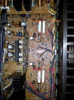
some pictures to help you to understand . Please let me know if you need more info
But i have big problem
i bought marantz amp pm-64 and its heating quite much ! I looked for shorts in the output terminals but its not so i am guessing its bias voltage Adjusting bias was not a problem for me in older models of Marantz but those service manual instructions are quite difficult to understand .
I have basic knowledge and training in electronics but my profession is in higher voltages , (Icelandic electrician) .
some pictures to help you to understand . Please let me know if you need more info
Attachments
Not sure what they are saying. They must not have had Google translator back then.
First, on an old amp, always check for DC offset.
Without a schematic, it is hard to give a recommendation. What do you mean by hot? Is the heat sink too hot to touch? Is one end hotter than the other? Does it play music?
First, on an old amp, always check for DC offset.
Without a schematic, it is hard to give a recommendation. What do you mean by hot? Is the heat sink too hot to touch? Is one end hotter than the other? Does it play music?
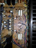
Its good enough to cook hamburgers after few minutes . This picture shows the emitter resistors and the pot mentioned in the second line of instructions.
I saw this also in the marantz 1090 service manual , "measure voltage between emitter Qxxx and Qxxx and adjust it to 12mA" ?! WTF
I know im supposed to be able to calculate with ohms´s law but does it apply there ?
I cant ask you fellas to spend time on this problem of mine but if you want i can send you the 9mb service manual .
Attachments
here is a link to the service manual . I have read some threads when its mentioned that this unit runs very hot and supposed to be quarter-class A ?
http://quality-and-performance.com/FILES/AUDIO-SERVICEMANUALS/MARANTZ PM-64II.pdf
http://quality-and-performance.com/FILES/AUDIO-SERVICEMANUALS/MARANTZ PM-64II.pdf
E=IR, not just a good idea; it's the LAW.
Yes it applies here and everywhere.
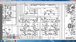
Your Re is .18 Ohms. So to get 12 mA, that would mean you want a 2.1mV drop across it. WAY under nominal class B. (26 mV at 140 mA) If it is running in a very heavy AB range, who knows what they chose.
The schematic says the drop across Re is 46mV. That is a bunch. I don't know what the "class A jumper" is, so under what condition it is 46mV on the NPN side and 36 on the PNP side. I don't know. Maybe that is their advertised class A for a watt or so.
It also tells you what to expect on the base of the bias spreaders. Again, under what setup condition I don;t know.
Are you sure you don't have a stability issue?
Are the voltages across all the Re's the same?
What are they?
Something could be amiss and be driving you to a rail.
Is everything the same right to left?
Yes it applies here and everywhere.
Your Re is .18 Ohms. So to get 12 mA, that would mean you want a 2.1mV drop across it. WAY under nominal class B. (26 mV at 140 mA) If it is running in a very heavy AB range, who knows what they chose.
The schematic says the drop across Re is 46mV. That is a bunch. I don't know what the "class A jumper" is, so under what condition it is 46mV on the NPN side and 36 on the PNP side. I don't know. Maybe that is their advertised class A for a watt or so.
It also tells you what to expect on the base of the bias spreaders. Again, under what setup condition I don;t know.
Are you sure you don't have a stability issue?
Are the voltages across all the Re's the same?
What are they?
Something could be amiss and be driving you to a rail.
Is everything the same right to left?
Sorry you misunderstood my ohms law question , i was meaning if i had to calculate the amps from my known 0.18ohm and adjust the voltage . English is my third language .
Im not sure what to measure now, i can pinpoint it on the sch where those numbers are you mention . But are those voltage drops (36mV and 46mV) between base and emitter?
The amp sounds nice, the heat sink near the power transistor is about 176°F - 80°C after 30 min run time mostly stable .
Before i plugged my Grado-ps500 (i love USA for this company) headphones in, i checked the Dc offset on the speaker therminals it was readling like 8mV both sides .
And regarding the heat , it´s quarter A amp.

English was not the native language of who wrote the manual either! Your English is far better than my Norse.
80 is hot, but if it is running a "quarter class A", I can see that as it would be sitting at a quarter amp if the 46 mV across Re is correct. That is like 32 Watts per bank at idle. Offset is good, so that takes a lot of worries away.
The 46 mV on the schematic I would NORMALLY take as referenced to ground. That is way higher than the 12mA , calculated as 2.1mV across each Re, or 4.2 mV across the spread which is what the instructions are saying to set it to. 12mA is VERY lean and will have high distortion. 46mV across Re is VERY heavy class AB bias. I suspect that is what it is when switched to "quarter class A" which is an advertising slogan for class AB instead of optimum class B bias for an emitter follower output of 26 mV. With no input, if you read 46 mV at the emitter of an output when in "class A mode" that is about right.
If it were mine, I might back it off a little, but I am very conservative in that respect. I spent many years in a failure analysis lab. It left me a bit shy on power. In any case, it would need to be out where it can get plenty of air flow. This is a case where those instructions for several inches around it make good sense.
Yea, love my Grado cans too.
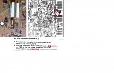
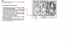
Read the manual. even more confusing as it does not quite match the schematic.
Anyway, you have a monster that looks very sweet. Marantz sure does not make them like that now. A good one for folks to watch for on e-bay.
Reading it, I had to laugh as it is so old they mention a VTVM! They say on page 3, 100mV emitter to emitter. You can do this with a modern high quality digital meter. That's even higher than the schematic!
I was thinking about recap the whole damn thing . Could i get in trouble with the bias if i do it ? What do you recommend me to do ? should i put it in repair shop for 100$ per hour?
anything you would advise me to do? for example running this procedure listed in the manual .
anything you would advise me to do? for example running this procedure listed in the manual .
Last edited:
If it were mine, and take this with all possible disclaimers,
Any electrolytic cap over about 7 to 10 years old is drying out and needs replacement. Considering the high heat, probably on the short side. So yes, I would recap. This is NOT a cheap thing to do. It should not effect the bias.
I would put a modern op amp in the pre-amp section.
I would bring it up on an auto-transformer to be sure nothing was amiss.
I would set the voltage, from emitter to emitter at about 80 mV, not the 100 they say. One thing I can be sure of, it was probably not correct when it left the factory, and after everything has aged, it is not correct now. I have owned over 30 amps. None were set correctly. Even my Parasounds, and they do try very hard.
The other alternative is to sit down and shut up. If it sounds good, play music.
wow the reading was about 200mV i forgot to turn off the loudness button for example i adjusted the voltage to 85mV between this double emitter resistor . And the amp is lot cooler just below 60°C near the power transistor not 80°C+ . I do not think its sounding better but the transformer buzz has got a lot less annoying The only thing im worried about now is the other pots the service manual mentioned . Shorting A class 25W pins and the AB pins . mabey should i leave it alone.
I wonder how the bias voltage got so ****** up
The only thing im worried about now is the other pots the service manual mentioned . Shorting A class 25W pins and the AB pins . mabey should i leave it alone.I wonder how the bias voltage got so ****** up
Next up . Recapping ! This amp sounds wonderful with grado ps-500 . And outshines marantz 1072,1090 and 1152DC witch i own .
Amazing that 27year old device with original Elna caps (at least they dont look good) is pulling so good sound !
Next step is to test it on Martin logans (another master piece from USA)
Amazing that 27year old device with original Elna caps (at least they dont look good) is pulling so good sound !
Next step is to test it on Martin logans (another master piece from USA)
Last edited:
Good design remains... good design. Not what DMH is making today.
I too love my Grado's, be they humble 80's. Squeals were one of only two commercial speakers my wife approved of. Vandersteen the other. It took me 30 years to build speakers good enough for her sensitive hearing. (Very close to the ZAPH SR-71, but with the aluminum tweeter driven by big Parasounds)
When I recapped my DH-120, I went oversize on the main bank, put in a much bigger HEXFRED rectifier, and snubbers on both sides of the transformer. Noise floor dropped by 8 dB and power line harmonics by 17. Then I got carried away testing it and to make the story short, it now has Exicon outputs. Hitachi magic smoke does not stay in very well.
Going through the catalogue of older Japanese designs, it was normal to underbias their universal, EF2 class AB amplifiers. Anything from 15 - 50 mA was typical. Bear in mind that THD in popular models was otherwise still around 0.1 - 0.5% and that can sometimes hide a lot of XO distortion.
The concept of optimum bias levels for any BJT amplifier design has taken decades to become part of mainstream thinking and education so don't be surprised that the rise and fall of home stereo power amplifiers was over before the neat theories were out there in books for all to read.
Oddly enough, Sony, Hitachi and others who also produced CFP output stage models, used high bias at 60 - 100 mA to squish the nasty crossover of a drifting low CFP bias - something manufacturers didn't seem to understand how to deal with back then. They managed to be unusually good sounding amps regardless of their glaring technical faults.
However output stages, even class A, that run over 60C, should be investigated. With an old amplifier, I would suspect that the thermal grease has dried up and powdered long ago. That means that the power amplifiers may not last long if used in class A. I suggest you unsolder and carefully remove the output transistors and insulating washers. Clean them thoroughly, preferably replacing the washers and insulating sleeves, then smear a thin layer of fresh insulating grease on the washer and refit - test the insulation of all connections from the heatsink before powering again. Make sure there is free airflow around any class A amp.
Being flatpack transistors, I should have said that you don't really have to unsolder them when they are all against one flat heatsink face but you will have to unbolt all of them. Not sure what type of insulation is in place there but you can obviously avoid this precaution if the insulation is silicone rubber (silpads), not mica/grease.
- Status
- This old topic is closed. If you want to reopen this topic, contact a moderator using the "Report Post" button.
- Home
- Amplifiers
- Solid State
- Marantz pm-64 mk2