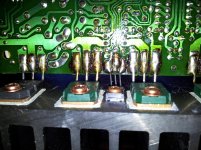
Picture 1 .Things turned out ugly when i started recap , i noticed this big fat uglyness ! Thou i managed to clean the darn thing up and fix solders i´m thinking about sparing the transistor replacement for later.
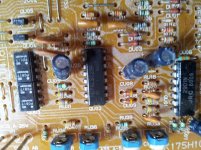
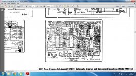
Picture 2 . Has anybody idea how to adjust those pots on the picture , they have something to do with class-A 5W and class-A 25W , I have the idea i am all over my head i have only basic training in electronics 🙁 . It would not be a problem if the service manual would not be so BAD!
it mentions that the bias adjustment is supposed to be done in 3 steps
Attachments
Last edited:
That is just old flux. Nothing to worry about.
Thermal grease looks OK. It is a mess to redo, so I would not. Old grease may contain beryllium oxide which is not good for you. Leave it alone if you can.
I don't know why you would replace transistors that had not failed. They don't age.
I think you are already biased in the quarter-a region. The long procedure is to put it into class B and set the low 18mA bias. Then return it to how you have it now with the higher bias. In other words, don't worry about it.
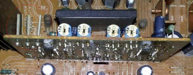
Thank you so much , you are a gem tvgeek. I cleaned the crap and fixed solders and recapped the whole damn thing in about 6-1/2 hours . And it sounds better than ever .
the DC out has dropped to almost 0mV and the annoying transformer buzz is almost non existent . And the hottest part of the cooling sink is about 53°C
the DC out has dropped to almost 0mV and the annoying transformer buzz is almost non existent . And the hottest part of the cooling sink is about 53°C
Last edited:
Hi,
I'm in the same state as you were Jonsig. Got a 64 Mk.II and it gets hot. I've set the class AB bias ~80 and kept the short permanently on AB.
Would you be so kind to explain what are the caps you've changed and what make.
Would it be a problem if I left the short the way it is ?
Thanks.
I'm in the same state as you were Jonsig. Got a 64 Mk.II and it gets hot. I've set the class AB bias ~80 and kept the short permanently on AB.
Would you be so kind to explain what are the caps you've changed and what make.
Would it be a problem if I left the short the way it is ?
Thanks.
Help required
The background:
Marantz PM64 Mk.II is designed to run the first 25W in class A and then slide into AB. The bias settings are done with three pins. Short the two pins on the right and adjust trimmers for class AB. Short the two on the left side and adjust trimmers for class A.
What would happen if the Class AB pins (right side) are shorted permanently. The reason I want to do this, is due to the heat in ClassA.
Thanks.
Attachments
Hello, I have concerns about this little monster. Everything is good, but the NGO is warming up. I do not read any voltage at the emitter resistance test points to adjust the bias. But there is sound, I am listening to music crazy. Please help, I do not read voltage in any way
 trtuncay - please stop posting the same thing over and over. Your posts need to be approved before they appear on the forum.
I recapped everything . except the power caps the 6800uf and the 10mF ones .
Hi Friends
please which bridge (A-B Class) can you elaborate? My little monster is getting very hot. Marantz has avoided giving the necessary details for this model. I couldn't see the voltage in the emitter resistance described by you and Marantz. But the device is working XXX is getting too hot. I don't know if this would be a problem.
- Home
- Amplifiers
- Solid State
- Marantz pm-64 mk2