A quick summary
CFA: amplifier topology that inherently supports fast rise/fall times and wide bandwidths. Distortion performance with the basic topology incl. EF3 can meet sub 10 ppm levels at 20 kHz. PSRR not as good as VFA topology, requiring additional filtering and regulation especially of the front end buffer/level shifter stage. Considered easy to compensate. Of interest in audio are the wide loop bandwidths, in some cases up to 40 or 50 kHz. Typical upper loop gain in the 60 dB range.
VFA: amplifier topology that in MC guise supports moderate to fast slew rates. LF dominant pole required to ensure unconditional stability. Alternative comp schemes allow slew rates and rise times to match CFA - eg MIC. PSRR performance of the basic topology better than CFA; noise performance considered better in some cases. Distortion performance when using advanced comp techniques and EF3 can achieve low single digit ppm levels (20 kHz). Typical LF OLG in 100dB plus range, dropping at 20 dB/decade such that at 20 kHz, 50 dB of loop gain may be available using standard MC. This figure may be increased using alternative comp schemes like MIC or TMC.
Last edited:
Alternative comp schemes allow slew rates and rise times to match CFA - eg MIC
Typical LF OLG in 100dB plus range, dropping at 20 dB/decade such that at 20 kHz, 50 dB of loop gain may be available using standard MC. This figure may be increased using alternative comp schemes like MIC or TMC.
Actually, MIC, or input inclusive compensation does not allow more major loop gain than ordinary Miller compensation.
Secondly, I suspect, but haven't examined this yet, that the compensation network that is required to make the input inclusive compensation loop stable may worsen PSRR dramatically.
My suspicions are founded in the fact that the similar shunt compensation network required to make the minor loop stable with Jolly-McCharles input cascode inclusive compensation ruins the PSRR.
Esperado,
In your summation of how you want the thread to go, you seemed to close the argument on the possibility that the VFA could sound better than the CFA. While I am not saying whether this is true or not, an openminded conversation that begins with a close minded statement seems interesting. I have listened to both the TSSA1.6 from member Sonya and the VSSA that I proto'ed using laterals. I preferred the TSSA over the VSSA. I agree that the amp "sound" extremely fast, with good pace and lots of air. I did not think that either performed as well in terms of tone or overall body in comparison to some Class A VFB amps I have built. I will proto the SSA next to see if it comes closer in this regard. I thought the VSSA would step closer than the TSSA, but it seemed to only give up some of its better capabilities in comparison, without gaining anything in return. This is not to say it is not an excellent amp, as I am just talking about personal taste. Of course we all know that everyone likes different colors, although I believe blue is the best.")
In your summation of how you want the thread to go, you seemed to close the argument on the possibility that the VFA could sound better than the CFA. While I am not saying whether this is true or not, an openminded conversation that begins with a close minded statement seems interesting. I have listened to both the TSSA1.6 from member Sonya and the VSSA that I proto'ed using laterals. I preferred the TSSA over the VSSA. I agree that the amp "sound" extremely fast, with good pace and lots of air. I did not think that either performed as well in terms of tone or overall body in comparison to some Class A VFB amps I have built. I will proto the SSA next to see if it comes closer in this regard. I thought the VSSA would step closer than the TSSA, but it seemed to only give up some of its better capabilities in comparison, without gaining anything in return. This is not to say it is not an excellent amp, as I am just talking about personal taste. Of course we all know that everyone likes different colors, although I believe blue is the best.
This thread is where we can discuss CFA and compare it to VFA in a friendly and constructive manner.
Thanks for opening up this thread, Bonsai. It is a good topic for discussion.
Cheers,
Bob
Somehow I suspect if I would put my MF80 VFA project (which had been designed for speed as well, with a fast output stage configuration and is capable of slewing in excess of 200V/us) inside a black box with a label saying "CFA MOSFET AMP", and invited all CFA proponents to listen to it, that the amp would receive universal acclaim.
Actually, MIC, or input inclusive compensation does not allow more major loop gain than ordinary Miller compensation.
Secondly, I suspect, but haven't examined this yet, that the compensation network that is required to make the input inclusive compensation loop stable may worsen PSRR dramatically.
My suspicions are founded in the fact that the similar shunt compensation network required to make the minor loop stable with Jolly-McCharles input cascode inclusive compensation ruins the PSRR.
I believe you are correct in that MIC does not allow greater global loop ULGF than ordinary MC.
MIC does not necessarily destroy PSRR, and in some cases may improve it. Take a look at the MIC implementation in my MOSFET power amplifier with error correction, http://www.cordellaudio.com/papers/MOSFET_Power_Amp.pdf. The MIC loop compensation is accomplished with a differential shunt series R-C across the differential outputs of the IPS. This thus does not compromise PSRR. Moreover, the MIC Cdom is referenced to signal ground on both sides, which eliminates one of the major causes of PSRR degradation in standard MC, namely that one side of Cdom is referenced to the power supply rail while the other side is referenced to signal ground (i.e., the VAS output node).
Cheers,
Bob
Carried over
Mine has and more and is 100% stable.
There is absolutely no way your amp. can have 80dB of loop gain at 20KHz and be stable. No way at all.
Mine has
and more and is 100% stable.Attachments
Ok that's a good idea.
I've opened a thread up.
Mods, you may want to move the CFA stuff to that thread.
All we need now are the posts moved from D Self's thread to here.
There are some 500+ posts from when the CFA debate started, and not all are relevant to the subject.
If someone wants to list all the post numbers as they stand now and put that in an easily readable form (for example a .txt file saying 501, 503, 506, 507 etc etc) then it might be possible to move them over.
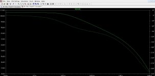
Beginner question again.
How do you extract this info from LTspice?
I have tried dropping the feedback shunt resistor to various values between 0.1 and 0.0001. Is this the correct way?
Yes, you have to run the amplifier "with no signal feedback". If the amp has offset problems these might be compounded and need a workaround (AC coupling or inclusion of a static DC voltage source to counter the error).
Yes, you have to run the amplifier "with no signal feedback". If the amp has offset problems these might be compounded and need a workaround (AC coupling or inclusion of a static DC voltage source to counter the error).
Thank you. I was getting some strange results. With 0.1R I was getting around 80dB then with 0.0001 I was getting a strange looking plot with a peak of about 20dB. Never considered the offset. Shall try again tonight.
Edit: This is on a CFA so not totally off topic
Last edited:
Member
Joined 2009
Paid Member
my first 2c:
1) It seems to me that both CFA and VFA can get the job done and the differences between them are only to be heard when comparing two different amplifiers (since they start with different topologies). Hence, more often than not, differences between them are difficult to isolate since there are many factors known and suspected to affect the sound of the result. Compensation is a key difference, as already mentioned above. There are many topological options that use CFA and many that use VFA which allow the designer to provide for certain performance parameters (e.g. PSRR, slew rate, harmonic profile, gain-bandwidth etc.) So I bring into doubt the usefulness of the question, which is better between CFA and VFA.
2) Without casting opinions about anybody in particular, I would imagine that a good results is achieved when a designer uses the tools he/she knows best, whether CFA or VFA, or indeed FETs vs BJTs, or SS vs Tubes - amplifier artists and engineers might do best when using certain approaches because this is where their talent and experience is.
Last edited:
Carried over
Mine has
I think Mikek is talking of global NFB and in this matter
he s right , you cant go over 30-35dB GNFB at 20Khz
without stability issues, of course the total feedback
including local loops can be much higher at said frequency.
30-35dB GNFB @ 20K for the CFA or VFA?I think Mikek is talking of global NFB and in this matter
he s right , you cant go over 30-35dB GNFB at 20Khz
without stability issues, of course the total feedback
including local loops can be much higher at said frequency.
I have tried dropping the feedback shunt resistor to various values between 0.1 and 0.0001. Is this the correct way?
If you drop this resistor you ll change the caracteristic
of the circuit , either it s a CFB and this will increase
the OLG or it s a VFA and this will change the feedback
loop phase/gain response.
Bigun, it seems i'm the only one, here, to had made a CFA version of a VFA amplifier in real world.
The problem is i have no way to share the sound in a forum.
I proposed that an expert in simulation (I'm not) take the L.C. VSSA schematic (with its permission, and because it is simple) and make a VFA of it, removing the F.B. resistances and adding an other input pair in LTP topology instead.
Trying to get the best results of this VFA version with appropriated currents.
Then publish its files and results for both versions.
It would be a good way to COMPARE. To see the differences in distortion, phase, slew rate, bandwidth, feedback levels etc...
A very useful collaborative work, full of interest. A reference.
I wonder why, no one from the VFA addicts, master of simulations witch were attacking-me about my models etc does not met the challenge.
30-35dB GNFB @ 20K for the CFA or VFA?
Whatever the topology , the higher the total gain the more
you ll eventualy have to "dump" high frequency gain either
using local linearizing loops or more brutaly with a shunt
at said frequencies.
Last edited:
- Home
- Amplifiers
- Solid State
- CFA Topology Audio Amplifiers