Member
Joined 2009
Paid Member
I seem to have too many projects on the go. My JLH10W amp is my current project, but I've decided it's best suited to the transformer in my HT amplifier.
So my HT amplifier, based on TGM1, needs upgrading (perhaps to something inspired by the LazyCat SSA) with some higher voltage trafo's I have. But it currently houses my TGM amp which I need to keep my HT in service.
So first, I need to re-build my TGM amp into a smaller box for temporary service in the HT system before it retires as a stereo. And so I arrive here….
If I'm going to rebuild the TGM, I may as well tinker with it first !
The TGM1 [http://www.diyaudio.com/forums/solid-state/140461-tgm-amplifier.html] is a simple Lin topology and sounds very nice, but it has some weaknesses - it doesn't have the greatest bass punch and it trades crisp treble for a softer sound with no harshness. it has some H2 and H3 engineered into it.
Next I modified it to TGM2 [http://www.diyaudio.com/forums/solid-state/145652-tgm2-amplifier.html] which used CFPs in the LTP. This brought noticeable improvement in bass punch and treble clarify, but at the expense of losing the easy listening pleasure - it was to harsh in the treble for my ears with my source and my speakers. It had no H2 or H3 engineered into it. I tried introducing some 2nd harmonic [http://www.diyaudio.com/forums/solid-state/168503-tgm-amp-goes-tubey.html] but this didn't go far enough to 'fix' it. A very nice amplifier otherwise but it's not the way forward now.
Next I went to the TGM3 [http://www.diyaudio.com/forums/solid-state/167369-designing-tgm3-output-triples.html] which uses a singleton input and low impedance voltage feedback. I put a CFP in the driver stage to shield the VAS from the non-linearity of the Class AB output stage and to provide a low impedance drive to the output. This sounds very good, I thought that was the end of the road. But thermal stability and dc offset are a nuisance with singleton inputs and I had to resort to a dc servo. It has a bit more start up 'cone movement' and the CFP driver requires a compensation cap on the negative driver which adds capacitive loading to the VAS. But this is the one to beat.
So, TGM4 will start again, from the TGM1 design.
Attachments
Last edited:
Member
Joined 2009
Paid Member
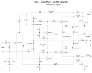
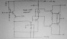
Here's the first sketch up incorporating some of the ideas from the old TGM threads.
The key features are:
- no CFP
- current mirror added to LTP to improve balance, accuracy and slew rate
- no CCS for LTP or VAS to keep signature 'sound' of TGM
- folded cascode + EF buffer for VAS
- separate front end power rails to reduce x-talk when using common trafo for both channels
The VAS is the main change from TGM1, it was discussed in the original TGM threads but my interest was renewed in common base with the lazy cat SSA thread. I remember it was part of the Reoender amp which I admire. But I feel it needs to be buffered because unlike TGM3 I'm not proposing to use a triple output stage. With an EF buffer I can lower the output impedance of the VAS and reduce the impact of Class AB output stage non-linearity.
It's a bit sketchy as to how the VAS should come together, in detail. Where should I tie the collector of the common base device - to the +ve rail ? My worry is what happens if this device turns on hard during clipping ? In a suggestion on a DX thread I suggested tying the collector of the beta-enhancer device to the output so that the voltage across the device was lowest when it was most stressed. So I'm thinking I should tie the collector of the common base device to the output.
Attachments
Member
Joined 2009
Paid Member
A couple more thoughts came to mind today.
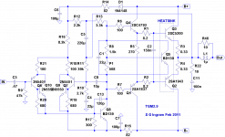
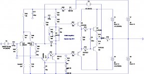
Firstly, the input impedance of the CB stage is rather low compared with a conventional CE VAS. I remember seeing a schematic on this forum that uses simple bootstrap of the LTP leg to address this (first/left attachment)
Secondly, I'm still a bit unsure i like the use of current mirrors. But I don't think I'll get adequate current balance without one with this kind of VAS to drive. The other way to build an LTP is the Rush Cascode. It does require careful set up to avoid d.c. offset issues and thermal drift. I'm not sure if I have the answer, but I've put a couple of diodes in the input side to address this. The TGM-Rush version is attached 2nd/right.
So this would be another way to realize TGM4. I'm not sure which version I like best, the Rush input or LTP input.
Attachments
Member
Joined 2009
Paid Member
Giving credit where it's due:
I would like to give credit to Greg for the bootstrap idea, the thread is here: http://www.diyaudio.com/forums/solid-state/65286-simple-killer-amp-2.html#post736240
and
I would like to give credit to Keantoken for drawing attention to the Rush Cascode, the thread is here:
http://www.diyaudio.com/forums/head...h-cascode-headphone-amp-jlh-output-stage.html
Hi Bigun,
In your RC circuit, how about a bootstrap cap from the junction of the two resistors on the collector of the bottom device to output, then the present collector connection from the same device moved to the base of the EF driving the output stage?
That way you remove the common base device, and maintain all the correct phase relationships for nfb.
Cheers,
Hugh
Hi Bigun
Take a look at the LTP biasing on this old Rush cascode amp.
4QD-TEC: Low distortion Audio amplifier
Take a look at the LTP biasing on this old Rush cascode amp.
4QD-TEC: Low distortion Audio amplifier
Member
Joined 2009
Paid Member
Thanks for the input on the RC version - I will give this some thought.
With the LTP input version, using common base VAS with current mirrors isn't obvious, so I invented a way to connect the VAS in a Lender topology using a current mirror.
Of course, we never invent here, we just reinvent and an hour later I found it here: http://www.diyaudio.com/forums/solid-state/194780-borbely-lender-true-symmetry.html#post2676013
However, I've been shy to use current sources and their associated ancestor, the current mirror, on the grounds that in real life they add non-linear devices with phase shifts into the amplifier.
I worked up a quick simulation of the common base VAS (attached) without a current mirror and it seems to work.
I've noticed a h.f. roll-off in the simulated OLG and my question is for this topology - from where does the roll-off arise ?
I also simulated a version with the grounded base device connected with the base taken off the 'left leg' of the LTP, a kind of simplified Lender (simplified because there's no EF buffer before the base connection). It also worked well but as Lumba Ogir pointed out in the original TGM thread, this also introduces miller capacitance back to that leg of the LTP unless the EF buffer is included which adds more devices into the chain. Nevertheless, what is attractive about the simplified single-device Lender topology is that it cuts out more parts. This might be something that can only be decided by listening since the difference between the simplified Lender and the version posted below are difficult to appreciate through simulations alone. I did find comments on this forum that Hugh has tried the Lender approach and didn't hear any sonic benefit.
I did a mental check on the bootstrap idea of Greg's. Of course, it doesn't work here. Firstly, the quick sketch I posted of it above has the bootstrap signal from the wrong side of the VAS slave device, and secondly this VAS is not a simple buffer like Greg's so the amplitude of the bootstrap signal doesn't match that of the LTP leg. Cross that idea off.
Did you notice the 'SandyK' resistor ?
Attachments
Member
Joined 2009
Paid Member
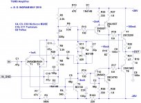
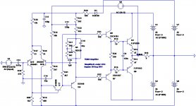
I thought I'd post up an schematic of my simplified Lender VAS idea. I like it for the fact it removes the need to bias the common device base even though it potentially introduces some miller capacitance to the left leg of the LTP. Simulations indicate an increase in OLG but stability looks very good - no Cdom required.
I also like that it makes use of both legs of the LTP, something that the Rush cascode can't do ( I haven't give up on the Rush ) and has the elegance of a design that takes a single ended input, converts it to a differential and then converts it back to single ended all with the purpose of providing a good error amplifier for gnf that maintains a stable dc offset over temperature. The amplifier can be dc coupled if desired (something else the Rush version can't do without additional devices).
The collector load of the common base device has been taken up to the top of the Vbe multiplier. This allows me to use a larger resistor which improves performance slightly. In fact, based on simulations this is a good take-off point.
I may need some clamping diodes between the different voltage supply rails so that the front end can't reverse bias the driver transistor base-collector junctions.
If you mean the NAD phono amp with RC - yes I noticed this in the thread Keantoken started but I don't know that they still use it anymore.Hi BigunLooking at your sketches I think the schematics of NAD 306 would be of some interest.
If you mean the Vbe multiplier device - yes, it needs to be in intimate contact with the output devices. In the past I have mounted them on the same heatsink. But my last build I used silicone to glue the Vbe device directly onto the package of one of the output devices and it gave me a more stable bias during warm up.Shouldn't the driver transistors (Q1 and Q4 in the LTspice simulation in post 1) be on the heatsink too?
Attachments
I didnt mean the rush phono circuit but if I remember correctly the Nad 306 amp uses something resembling your second post. I think the ef is used before a folded cascode but id have to dig out the schematic. The nad interested me in some years ago because the single ended folded cascode produces the the so called prefered harmonic structure according to hiraga and this even using a CCS as load. THD figures are nothing to brag about but they still fairly low.
Looking at post 10 there is potential for a ef to increase OLG and lower THD, Ive used something very similar to this scheme in one of my amps but with mosfet combination.
Looking at post 10 there is potential for a ef to increase OLG and lower THD, Ive used something very similar to this scheme in one of my amps but with mosfet combination.
Hi Bigun,
I am surprised that your ratio of R99:R19 is so low. Normally, if I am reading the topology correctly, this ratio is ~10:1.
But Q17 is running at a very low current of ~400uA due to the high value of R41. This may account for your low ratio. Do R37 & R38 pass equal quiescent current?
I am surprised that your ratio of R99:R19 is so low. Normally, if I am reading the topology correctly, this ratio is ~10:1.
But Q17 is running at a very low current of ~400uA due to the high value of R41. This may account for your low ratio. Do R37 & R38 pass equal quiescent current?
Member
Joined 2009
Paid Member
if I remember correctly the Nad 306 amp uses something resembling your second post
If you have the NAD schematic handy and can post the relevant section I'd be interested to see it.
Looking at post 10 there is potential for a ef to increase OLG and lower THD, Ive used something very similar to this scheme in one of my amps but with mosfet combination.
Can you post your scheme here ? I'm not sure how much more OLG we want, I'm starting to get nervous about stability with reactive loads - it looks fine into a resistor but less so into 20nF. I'm toying with TPC phase lead - it buries the x-over distortion but is more complex.
Hi Bigun,
I am surprised that your ratio of R99:R19 is so low. Normally, if I am reading the topology correctly, this ratio is ~10:1.
But Q17 is running at a very low current of ~400uA due to the high value of R41. This may account for your low ratio. Do R37 & R38 pass equal quiescent current?
Yeah, these values are a guess right now. The low current through the common base device (about 600uA) may not be helping but there's a tradeoff - as the load resistor gets small we lose gain - again, I may need to play with that to avoid making stability a challenge. What would you recommend, and why ?
Member
Joined 2009
Paid Member
Yes, the ratio of the resistors in the legs of the LTP depend on the current through the VAS since this current is dumped directly into the resistor in the right-leg of the LTP. The question is what is the optimal current for the common base VAS device ? I tend to think higher than 600uA would be better. With a 2k4 collector load resistor the current is just over 1mA and the LTP leg resistors are 1k2 and 365R.
Last edited:
Member
Joined 2009
Paid Member
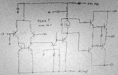
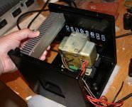
Here's the box for the prototype- trying to use up old 'junk'
The ex-Yamaha trafo has one c.t. secondary with19-0-19 a.c. for the output stage, filtered to +/- 27V.
Same taro also has a 0-33 a.c. secondary for front end, voltage doubled, paired with a virtual earth - regulator combo to give around +/-38V
OR
voltage-triple and regulate down to +/-53V. The VAS output will be diode-clamped to the +27V output rail and so would swing at most from +27 to -53, that's 80V which is at the limit for the BD140 (Vceo=80V)
- What Do You Think too risky ???
Heatsinks…
I've a pair of small heatsinks, one of them is shown in my hand, each giving 2degC/W per channel. With +/-27V rails this might just do.
Attachments
Nice little case, perfect for a low power amp.
If you decide to go for a classical single differential topology, improvements
follow a logical path that indeed lead more or less to the schematic that is
ubiquitous by there and whose main vulgariser is D. Self.
At first , you try the classic minimal schematic as the DX ,
then , in search of more linearity the first thing to do is to
add a current mirror , but then an buffered VAS seems mandatory
to extract the expected perfs that are greatly improved by using
a CCS for the differential, and that s it, we have a "blameless"....
As such, the maximal perfs of this circuit are extracted and unlikely
to be improved by any tweaking, as contrary to many poster s claims,
the eventual modifications just bring cosmetics changes if not willfull
non linearities that will help to forge a questionnable "sound signature",
a concept that is somewhat strange since a good amp should have
no "sonic signature" at all.
Another route is to go for a symetrical differential , but then one must be
cautious since there s inherent difficulties to make these circuits work correctly,
not counting that high perfs are not as easy to reach that with the usual blameless,
yet, this is my topology of choice and so far, all the ones i did build did work perfectly.
Anyway, these two topologies are the best to date linearity wise , and i m surprised
by the number of half designs that are branded "musical" while in fact thay are
at least one order in magnitude below these proved concepts.
So good luck with your design, and i hope that this post helped you to define
a winning strategy...
Member
Joined 2009
Paid Member
I'm not sure I understand all that you say - but I do agree, there is a point of diminishing returns where additional complexity brings questionable benefits. For me, I'm just not smart enough or willing to invest the time to develop complex amplifiers.
I do like the way that such a simple topology as TGM4 has the potential to sound very good indeed. And as any amplifier is one small part of the chain of music reproduction our ears will hear it seems too limiting to believe that any one amplifier will satisfy all people equally well.
I continue to learn a great deal from reading what D. Self has written, and along with other knowledge it allows us to have the ability to do some engineering. Like a photographer who knows his equipment and chemical film processing to great depth. But then I like to apply myself to building amplifiers that leave room for personal expression. Like a photographer.
p.s. I don't like CCS or current mirrors, no blameless lies in my future
Last edited:
As such, the maximal perfs of this circuit are extracted and unlikely
to be improved by any tweaking, as contrary to many poster s claims,
the eventual modifications just bring cosmetics changes if not willfull
non linearities that will help to forge a questionnable "sound signature",
a concept that is somewhat strange since a good amp should have
no "sonic signature" at all.
Anyway, these two topologies are the best to date linearity wise , and i m surprised
by the number of half designs that are branded "musical" while in fact thay are
at least one order in magnitude below these proved concepts.
Im afraid youre wrong here, with just one part change and not adding anything to the blameless the performance of the blameless can be improved, this was well known since 1987, even before Self published his findings in his papers
.Self doesnt know it all, not yet anyway, I bet in his next edition this part change will be shown as option although it changes the sound of the amp quite a bit and the reason I have used it for over 15 years. Also regarding the vas it is possible to lower THD if that is your perogative by upto 30 % at low and 25 % at high frequencies better than blameless if you follow more modern technology (1994) and without reverting to TMC or TPC while using only one more device, (you wont get there if you thinking of conventional cascode or hawksford cascode). All you need to do is think outside the box.
Bigun, Im not sure what THD figures youre aiming at but I can see that a EF before Q17 could be useful. In my case I have nothing against high feedback designs, they can sound as good or better than low feedback types. Last year on of the most raved about amp in the audio press was a new lavardin, the memory distortion concept amp, it according to some, best amps costing 4 and 5 times its price and including various tube amps. The lavardin costs about 4000 euros.
I have the Nad schematics but Id have to send the whole service manual, Ill see what I can do tomorrow.
I have the Nad schematics but Id have to send the whole service manual, Ill see what I can do tomorrow.
- Status
- This old topic is closed. If you want to reopen this topic, contact a moderator using the "Report Post" button.
- Home
- Amplifiers
- Solid State
- TGM4 amplifier