Ah! Thank you, Shaan!
I would like to, if my first attempt is a success, make a modular amp and try different output sections...for example, I wonder how a Sziclai pair would work here, or if it would ruin the performance or if it is just impossible to use it...for that, I will have to study first what the *** is a Sziclai pair, to begin with
I know this is becoming a long thread, but as far as I remeber, there were someone who did exactly that and proposed several output configurations.
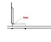
Very classical. It is always a good precaution to fold the gate's leg 90° apart from the Drain/Source ones, shorten-it to the minimum and sold the gate resistance directly on it.... oscilation... due to stray capacitance between gate/source and heat sink.
Attachments
Hello,
Is the 10 uF capacitor on Shaan's schematic not needed on the very nice PCB that Alex designed for us?
A capacitor is necessary for DC isolation of SSA from music source which may not have very low offset and may alter the input bias current balance resulting in dead speaker due to offset. It also ensure a set-and-forget setup. Alex has made space on the board for this cap but with reduced value, which may decrease bass response. 10uF is a bit large I know. You can use a 4.7uF with almost equal bass performance. Also, although I used a bipolar electrolytic here, I strongly reccommend a film type(MKP, MKT, PAPER IN OIL etc.).
Elegant!
Thanx for the great tip. I will always follow this from now on.
Very classical. It is always a good precaution to fold the gate's leg 90° apart from the Drain/Source ones, shorten-it to the minimum and sold the gate resistance directly on it.
Thanx for the great tip. I will always follow this from now on.
Yes, I see thats what I thought Shaan, just wasn't sure. Thank you for responding to my question about it. Shaan, you are one of the best P2P implementers I have seen in along time! I wish I could just watch and study your tecnique while you build something Like this project and others!
This thread along With along with the TSSA posting's, really is showcasing some very talented artists.
This thread along With along with the TSSA posting's, really is showcasing some very talented artists.
Shaan, you are one of the best P2P implementers I have seen in along time! I wish I could just watch and study your tecnique while you build something Like this project and others!
Yes,his work deserves credit..
Cambe,
You have to draw a one layer PCB layout and just copy it to the breadboard...
It`s relatively simple.. Needs allot patience, Just like fine needle work
Yes, I see thats what I thought Shaan, just wasn't sure. Thank you for responding to my question about it. Shaan, you are one of the best P2P implementers I have seen in along time! I wish I could just watch and study your tecnique while you build something Like this project and others!
This thread along With along with the TSSA posting's, really is showcasing some very talented artists.
Yes,his work deserves credit..
Cambe,
You have to draw a one layer PCB layout and just copy it to the breadboard...
It`s relatively simple.. Needs allot patience, Just like fine needle work
Thanks for the kind words. And as BenY said, it takes patience. However, I don't start with a pcb design and copy to the breadboard, instead I just go with the visuals of the schematic and put the components as they are visually situated in the schematic and in the end I get a design. It always works and errors can be eliminated, as all the boards I assembled has worked without letting the smoke out of the wire. I think anybody can make a decent P2P when the schematic is as beautiful and natural as the SSA. Credit goes to all the kind hearted contributers and specially to LC. He gifted me and many with the sound we look for.
I know that electrostatics have bad reputation and it is justified on the long time (~ 10 years life). But, regarding their "sound", there is nothing i fear when i use them as coupling capacitors. The only complaint we can make is their self at Hf, but, in the input, adding an extra filtering little pole brings more benefit than inconvenience.I strongly reccommend a film type(MKP, MKT, PAPER IN OIL etc.).
Never, never use mica or tantalum ones in the signal path, because of their resonances.
Just take care to get a nice max voltage margin (> 30%).
For filtering, a common, -and bad- practice is to parallel big electrolytics with little film caps. It will bring a resonance in the impedance curve because of the self of the electrolytic. The best practice is to parallel little caps instead of using big values. (Impedances are lower and they divide themselves).
16X1000µf will gives an impedance ~8times lower than a big single 10 000µf one.
Because each little one has more than half the impedance of the big one at hf, and they divide their impedance by 2 each time you double their number.
If you want to parallel various values, never go more than a 1/10 difference: 1000µf +100µf+10µf+1µf. electrolytics Then, you can add your 0.1µf film capacitor for hf.
On my side, i avoid any "high end" "audiophile" capacitance like hell.
On the contrary, i find a big difference with resistances qualities. I always use metallic film ones instead of carbon. I found carbon to give a "grainy sound".
For high power resistances, where HF is critical (gate resistance), avoid wired ones, and use thick film instead. Wired ones are very good for power, before filtering caps, because they are low priced and they add their self to the hf filtering for free ;-).
Just my two cents.
From listening experience , amp with multiple caps (16x 5000uf ) don't have as good a bass as (4x20000) , sounds weaker or put another way , everytime I have heard an amplifier that has exceptional bass , slam and control , it is never with large quantity of small caps , in the PSU...
It depends on the cabling; wires and CI tracks thickness, distances etc...I used to feel the same than you, then, i tried to sold my caps on big copper bars...From listening experience , amp with multiple caps (16x 5000uf ) don't have as good a bass as (4x20000) , sounds weaker or put another way , everytime I have heard an amplifier that has exceptional bass , slam and control , it is never with large quantity of small caps , in the PSU...
Of course, if the wires between the PSU and amp are long, because of the self of the wires, you will lose any benefit using several caps instead of big ones, and, if you add an extra filter on the amp ...
I believe the best is to use big caps in the PSU, and several (4 on each side) little caps as extra filtering on the amp board (total value=1/10 of the value of the PSU ones) ? And big big wires to carry the power between boards.
Did-you mean "breaking time" ? I found that, letting an amp during a night on a generator and charged by a resistance at near full power is enough ? Like for breaking loudspeaker suspension.mikelm said:In your experience, how long does it take for an electrolytic in the signal or FB path to "run in"
If you means heating time at each listening seance ? It depends of your life time ;-). Half an hour is enough to stabilize the temps, i think, but i feel be better to listen to music during half an hour than to loose my time waiting for some kind of perfection ? ;-)
Regarding those psu choices, many audiophile prefer to use 2 mono amps instead of a stereo one. The difference is each one use his own PSU. I use to feel the stereo image less stable with mono amps.
Easy to undestand: each amp will vary its efficiency during big power transients, not at the same value on each side, and intruments will move on stereo localization. A common PSU for both chanels will reduce the phenomena. Reason why i recommend a 1/10 value for the amp board power filtering caps.
ESP,
I'm inclined to agree on big in the PSU and then smaller as close as possible to the outputs.
I was looking at FMA , Newest and greatest amp , the FMA118 and suprised to see Manny favoring one large transformer over 2smaller ones for the PSU. Supposedly one large is superior to 2 small ...!
Thoughts ...?
About breaking amps, each of us do not always have big 50w 8 ohms resistances.
A tip i used in the manufacture i worked in long time ago:
We used to break each amps, before to 'pass them" charged by a 50w 24v truck headlight bulb at 50w of output power
.
It is low priced, and, if you see an bulb not lighting in the morning, you know in one sight that the amp has failed (or the bulb).
And, if, when you bring the source to 0V, if a bulb is still lighting, that the amp oscillate, or one side of the push pull is in short circuit.
Agree. For the same reason: Using a single transformer help keeping the both rails symmetrical during transients.Supposedly one large is superior to 2 small ...!
Thoughts ...?
This said, X3 the required VA seems a good compromise: i use a 1000 VA for my 2X150w amps. I use > X2 with SMPS.
ps: One more advantage, using paralleled caps, is to linearize their value: Electolitics caps have great value disparities, paralleled them help to randomly equal the total value on both rails. (Is this understandable, despite of my poor English ;-)
Last edited:
I prefer film type caps for input coupling. In my short ~10 years life with audio diy electrolytics has always failed me here. I have been using 1uF Siemens MKT polyester with my DOZ amps with 100k input impedance for the last 2 years for their apparently better HF response, placing an electro in its place makes the sound dull. I have placed order for a dozen of 10uF 630v rated large cylindrical polypropylene things. Hoping magix. Will update when they arrive.
Anyways the 10uF electro is on fire with SSA right now with the following, each of which has challenging HF content:
Keith don't go - Neils Lofgren
After hours - Ronny Jordan
Red dust and spanish lace - Acoustic Alchemy
The brightness of these days - Kyoto Jazz Massive
Time - Stella Starlight Trio
Flying, part 2 - Keith Jarrett
Glass room - Speak (synth dnb track, but great for both bass and treble test, if you have not tried it yet I suggest you do so ASAP)
and many more...
No doubt.My preference is no cap , nada , zero, zilch .....
And a protecting circuit is less expensive than golden diamond audiophile caps ;-)
Last edited:
No doubt.
And a protecting circuit is less expensive than golden diamond audiophile caps ;-)
Your speaker protection idea is the most complex one I have seen on this planet, but it fails to eliminate a (cheap?) relay at the amp output.
I have checked big names high end amps, and yes, almost all of them use relay at output. Different approach (such as used by Pioneer if I'm not mistaken) is to ground the input and output of the amp when DC is detected at output. I don't know if this approach is effective enough but why not?
- Status
- This old topic is closed. If you want to reopen this topic, contact a moderator using the "Report Post" button.
- Home
- Amplifiers
- Solid State
- Simple Symetrical Amplifier