 I get the same number: 300Wrms@4ohms -> 8.66A rms and it's 1/2wave so each rail fuse would be minimum 4.33A and prob. rounded up to 5A, just like they used in the SC Studio 350.
Where does 300W of music power come from?
I was intending to post a shorter quote consisting of just the first sentence, but thought again and decided that fairer to show the whole and thus not bias the question.
If they built and tested the power output into 4r0 and 8r0, then publish the actual power outputs into the respective test loads.
Why invent a fictitious "music power"?
ULD MK2 -> MK3 Upgrade
The version I built worked well, I followed all the instructions that came with the K5151 kit, but in my opinion it is the least of my many-amps, in terms of listener satisfaction.
I only have a few criticisms of these ThermalTrak kits and the instructions that come with them. I do not mean to insult the designer, but think the whole idea was rushed into production at a time when it should have still been on the workbench at silicon chip.
From an enthusiast kit builders viewpoint I would like to say the following:
The instructions are essentially photocopies of the relevant Silicon Chip Magazine articles, some of the printing is illegible and of course there is no coloured ink, this is a BIG issue when it comes to tracing tracks through the two layers and apparently, unlinked vias. - In the magazine, it is still difficult, but there are many colours and shades to help you find what you are looking for.
Whilst on the subject of the K5151pcb, I can see no real need for two layers. Secondly, I am very disappointed that the pcb designer placed one huge cluster of vias directly under the output resistors on the LHS of the board when you are looking at the heatsink's shiny side, a location where we attach the multimeter (to measure Iq). These vias are part of the positive rail - short the resister to the via and watch your dream go up in smoke. That smoke really stinks and the soot from the plastic shoots out and scorches those giant 85 degree 1000uF rail caps that sit next to the heatsink.
Whilst on the subject of Iq adjustment my particular board was upgraded to MK3 standard using the instructions set out in silicon chip sept 2011 (exactly). The 1k trimmer on the vbe multiplier had no effect on Iq whatsoever - which left me wondering why I went to the trouble of etching the pcb which hangs like a penis from the top of the heat-sink. The wires of which attach to various pads across the length and breadth of the pcb and look like the type of antenna used for a ham radio base station. Luckily for me the Iq was spot on 60mA for all four output transistors on each board - that is 6mA across each of the 0.1r output resistors.
ThermalTrak transistors have five legs: so when you smoke all four of them whilst doing the Iq adjustment, you are going to have a bit of trouble getting them out of two layers of track-work. OK you might get away with smoking the two pnp's but you cant get the npn's out to test them, without cutting the 5 legs on each device and removing the stubs singularly. They are very expensive to buy, and if you are using the Vbe of a BD139 then the ThermalTrak device is obsolete.
Finally, If any of you are as careless as me when you do your Iq adjustment, don't expect the Silicon Chip K5124a1 speaker protection module to do anything until at least 500mS after the ThermalTraks have vented and the 5A fuse has blown. Silicon Chip recommended a 6.5A but I used a 5A. Although I believe the fuse blew & the relay tripped simultaneously after the event and it seemed like a second or more later.
On the topic of speaker protection; I have reworked the speaker protection module for my A-class 20 watter using the Self method of putting a zener in series with the rectifier across the coil of the relay and reducing the working voltage of the coil to about 75% of it's rating. These are rough figures but I can assure you that the module will trip very fast indeed if you tinker a little bit. I dont have a digital dual channel scope (Like the Gurus a SC) to check the timing but it is audibly fast. In fact it is so fast as to be almost indistinguishable from the snap of the main power switch when the amp is turned off and the circuit detects a missing ac pulse and opens the relay to kill the 'would-be' thud from your expensive speakers. My next speaker protection module will have two relays (cheap and reliable) one to disconnect the speaker and the other to rapidly discharge the power supply capacitors through a pair of resistors to ground. The two smaller relay coils in series will use little or no more power than one large one.
Someone else in this thread mentioned that big 47uF np cap in the HP input filter and using the designers logic a physically large capacitor can suffer extraneous signal pick-up (from the SC article, with reference to the NFB capacitor). The 47uF that I have in my board measures 13mm in diameter and 20mm in height. If I were to build another board I would use a 33uF np like the ones I got from Rockby Electronic Components online store (they work really well in the speaker protection module also). They measure 10mm diameter and 15mm height. On the input of the ULD, the 33uF in combination with the existing 12k filter component shifts the frequency slightly from 280mHz to 400mHz and I guess that this cheap component would still have a low impedance at the 50Hz signal used for the comparison between 4.7uF and 47uF. Once again I have no expensive gear to measure this impedance but I suspect the logic is pretty right.
I have learned a great deal about amp design from this project and indeed from the designer himself, so it's not all bad. The amp did sound ok until I blew it up, but I will not be repairing it due to the expense of replacing the output transistors (and possibly another pcb). This is a real shame because I have designed and built a soft starter for the power supply, built a preamp and installed it in the enclosure, and wrapped 6 toroidal cores with 1.28mm encu until my fingers blistered (ripple control). I was intending to take it around to my mates place (he has a good scope) to see if I could observe a reduction in the 1V/100Hz ripple depicted in the magazine.
Anyway, I hope my little post-script will help someone who is still game to build it.
My apology to SC

Alright I was having a bad hair day yesterday! The 1k trimpot in the Vbe multiplier does actually work, but I only discovered this yesterday. For some reason or other my amp(s) both ran at 6mV/0.1 resistor at the get-go, I wound the pots up and up and up to what seemed to be 20 1/2 turns and dared to go no further, assuming I had made a blue when drilling out the pcb track joining the NJL's diodes.
I put the safety resistors back into the fuse holders this morning and tried once more - to find (much to my surprise) that the pot finally increases the voltage between the drivers on the last turn before it starts to click click, where it becomes very peaky and a gentle hand is required. I now have 100mA through all the output transistors.
Whilst on the subject of Iq adjustment my particular board was upgraded to MK3 standard using the instructions set out in silicon chip sept 2011 (exactly). The 1k trimmer on the vbe multiplier had no effect on Iq whatsoever - which left me wondering why I went to the trouble of etching the pcb which hangs like a penis from the top of the heat-sink. The wires of which attach to various pads across the length and breadth of the pcb and look like the type of antenna used for a ham radio base station. Luckily for me the Iq was spot on 60mA for all four output transistors on each board - that is 6mA across each of the 0.1r output resistors.
Alright I was having a bad hair day yesterday! The 1k trimpot in the Vbe multiplier does actually work, but I only discovered this yesterday. For some reason or other my amp(s) both ran at 6mV/0.1 resistor at the get-go, I wound the pots up and up and up to what seemed to be 20 1/2 turns and dared to go no further, assuming I had made a blue when drilling out the pcb track joining the NJL's diodes.
I put the safety resistors back into the fuse holders this morning and tried once more - to find (much to my surprise) that the pot finally increases the voltage between the drivers on the last turn before it starts to click click, where it becomes very peaky and a gentle hand is required. I now have 100mA through all the output transistors.
Farmer,
you could instead have measured the bias voltage. This changes progressively as you adjust the VR in the multiplier.
Try it now.
You will see that as the Vbe of the output device approaches 500mVbe that the outputs turn on
Most of the VR adjustment is in bringing that Vbe up from 0mVbe to 500mVbe.
you could instead have measured the bias voltage. This changes progressively as you adjust the VR in the multiplier.
Try it now.
You will see that as the Vbe of the output device approaches 500mVbe that the outputs turn on
Most of the VR adjustment is in bringing that Vbe up from 0mVbe to 500mVbe.
listening to the uld mk 3
Good day Carl. So far I have found the amp to be a bit on the bland side. If I play a good recording (say something from Sony) it sounds great. But if I play old blues stuff recorded by Chess records 25 years ago it sounds average to me (unlike my Hitachi SR802 for instance). Most microphone recordings sound pretty average also.
I have just bought one of those cheap L20 amps from ebay (the ones with 5200 & 1943 pairs - so I will do a comparison before Christmas.
I can see it!
Once again you have hit the nail on the head Andrew! I will take a look at it after tea.
Cheers and thanks.
Farmer,
you could instead have measured the bias voltage. This changes progressively as you adjust the VR in the multiplier.
Try it now.
You will see that as the Vbe of the output device approaches 500mVbe that the outputs turn on
Most of the VR adjustment is in bringing that Vbe up from 0mVbe to 500mVbe.
Once again you have hit the nail on the head Andrew! I will take a look at it after tea.
Cheers and thanks.
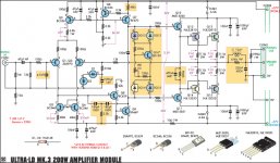
Schematics of Ultra-LD MK.3 from siliconchip's own web page.
http://archive.siliconchip.com.au/static/images/articles/i1125/112517_10lo.jpg
Will just paste in the following lists of silicons "as is" from a video relating to MK.IV upgrade, please check if they are suitable.. 2SA970/BC550/BC560, 2SC4793/2SA1847, 2SC2344/2SA1011, Sanken SC3264/2SA1295
http://archive.siliconchip.com.au/static/images/articles/i1125/112517_10lo.jpg
Will just paste in the following lists of silicons "as is" from a video relating to MK.IV upgrade, please check if they are suitable.. 2SA970/BC550/BC560, 2SC4793/2SA1847, 2SC2344/2SA1011, Sanken SC3264/2SA1295
Attachments
UF4004 or some sort of diode-connected transistor would be more like it... but how are you going to get these into the transistor package? That was the main selling point for these ThermalTrak devices. I guess you could get reasonably close if your finals have a case style with a tab to attach to, it probably still is going to be slower though.
- Status
- This old topic is closed. If you want to reopen this topic, contact a moderator using the "Report Post" button.
- Home
- Amplifiers
- Solid State
- Silicon Chip ULD Mk3 amp - 0.0006% distortion