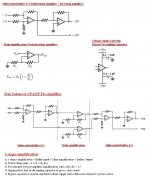
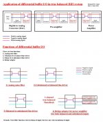
My new design of differential buffer I/O board for fully balanced design!
Material rough estimation: Dual OPAMP x1, Resistor x 6, Socket x2 pcs
(Reference: http://jensentransformers.com/an/an003.pdf)
Material rough estimation: Dual OPAMP x1, Resistor x 6, Socket x2 pcs
(Reference: http://jensentransformers.com/an/an003.pdf)
Attachments
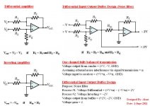

To have a fully differential interface with ICs, with maximum CMMR, you will need instrument-type arrangement on first chip, with three chips. Or a balanced IC, which does have 3 instrument chips inside. You may also need R and C trimming.
To have a fully differential interface with ICs, with maximum CMMR, you will need instrument-type arrangement on first chip, with three chips. Or a balanced IC, which does have 3 instrument chips inside. You may also need R and C trimming.
Dear carlmart,
First of all, thank you for your comment. For self-improvement, I always listen to anyone's idea. Accept or not, subject to the ground of statement. For your statment, please show your theory, calculation or something else to support your reason.
My design is based on Jensen's article as reference which was well developed for a long time. If wrong, then Jensen's idea is wrong too. Anyway, thank you for your writing.
go and read this para again.A BALANCED input or output uses two signal conductors
which have equal impedances to ground. Balanced inputs and
outputs are widely used in professional equipment because the input
differential amplifier can, in theory at least, totally null its response
to ground noise which exists equally on both signal lines. Examples
of typical circuits are shown below.
Because of its low cost and small size, this "active balanced"
differential input circuit (or some variation of it) is very widely used.
The pairs of 10 kS resistors are trimmed to match within 0.01% in
order to null response to ground noise. When used in real-world
systems, however, a major drawback of this circuit is its exquisite
sensitivity to unbalances in the output (source) impedances of the
line driver. This seriously compromises ground noise rejection or
CMRR (Common-Mode Rejection Ratio) of the system.
Then look at fig2.3
Your interpretation is wrong, not Jensen.
Hi AndrewT,
Thank you for your explanation. Long time no talk, my last talk with you back to year 2008 at this thread http://www.diyaudio.com/forums/chip...ity-highpower-amplifier-reference-design.html with Lineup too. Did you retire or still teaching at school in Scotland?
My buffer I/O design is an effective tool to reduce noise, theorically at zero noise level, but very simple design and extremely low cost. I am just an audio amateur, thus make it “Not-for-profit”.
If you really want a fully diff I/O with good CMR (after all, why bother if you get only part of the benefit), look at the OPA1632. There are more like that, which would perfectly fit your need.
Or, look at the 'InGenius' chip from THAT Corp. Designed by Bill Whitlock, who took over Jensen from, ehhh, Jensen, many years ago.
jan didden
Or, look at the 'InGenius' chip from THAT Corp. Designed by Bill Whitlock, who took over Jensen from, ehhh, Jensen, many years ago.
jan didden
Dear Jan Didden,
Appreciate your comment. I believe that the design concept of TI’s OPA1632 and my buffer I/O is similar. But, I do not know for any difference or exactly equivalent unless TI discloses the secret of circuit topology inside chipset. TI is only willing to tell you the application of chipset or I accidentally disclose the secret of TI. TI has just acquired National Semiconductor to be the market leader in this industry. I am a result-oriented person, the best choice is the one best fit to my goal, but not insisting in my design. One advantage of own design is better customization and flexibility. TI OPA1632 or my buffer I/O which one is better is not important, the most important is that both of our approach is correct.
I would like to remark that noise damages the quality of sound in analog signal transmission. But, it does not guarantee a good quality of sound even though you achieve the goal of theoretical zero noise level. The first priority depends on the source of sound that is the one in master recording room and the post processing unit to fit your taste of sound including digital module, multi-stage analog amplification module and the electro-mechanical vibration of speaker which is an integrated system approach in signal modeling.
Be careful with phrasing concerning zero noise. In a perfect world a balanced differential scheme can reject low frequency noise pickup, but there is a price to pay. The system will typically have a higher internal (thermal and internally generated) noise level than if it were single ended! It's very appropriate for professional sound systems in contaminated environments, but IMHO doesn't offer any advantages in a home set up.
To work right you need identical impedances on both lines, something the single opamp differential amp doesn't have. As said above, you need to go to either the three opamp instrumentation arrangement, or there's a two opamp cascaded opamp circuit that can probably be used. It's also important to understand the difference between differential signals and balanced differential signals because that will make the impedance issue clear to you.
To work right you need identical impedances on both lines, something the single opamp differential amp doesn't have. As said above, you need to go to either the three opamp instrumentation arrangement, or there's a two opamp cascaded opamp circuit that can probably be used. It's also important to understand the difference between differential signals and balanced differential signals because that will make the impedance issue clear to you.
Be careful with phrasing concerning zero noise. In a perfect world a balanced differential scheme can reject low frequency noise pickup, but there is a price to pay.
Dear Conrad,
1) "a price to pay"? I suppose not to pay to anyone unless patent issue, but people need to pay to me. Just kidding!
2) My buffer I/O is in conceptual design stage, need fine tuning, but not a big change. Your comment is valuable and will be put into consideration.
Nice to speak with you.
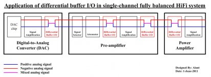
Here are some examples of audio amplifier using buffer I/O device such as OPAMP or transformer:
Pre-amplifier:
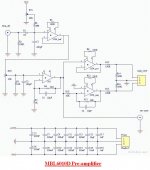
1) MBL6010D Pre-amplifier (Buffer NE5534 + Amp AD797 + Balanced Output NE5534)
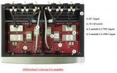
2) Jeff Rowland Corus & Criterion Pre-amplifier (TI OPA1632 + Lundahl LL7902 + Lundahl LL1588)
Power Amplifier:
3) Wured4Sound SX-1000 Power Amplifier (Buffer I/O + B&O Icepower 1000ASP)
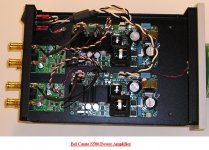
4) Bel Canto S500 Power Amplifier (Buffer I/O + B&O Icepower 1000ASP)
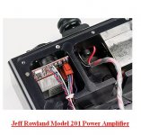
5) Jeff Rowland Model 201 Power Amplifier (Model 201 Lundahl LL1545A + Icepower 1000ASP or Lundahl LL7902 + Icepower 1000ASP)
Pre-amplifier:
1) MBL6010D Pre-amplifier (Buffer NE5534 + Amp AD797 + Balanced Output NE5534)
2) Jeff Rowland Corus & Criterion Pre-amplifier (TI OPA1632 + Lundahl LL7902 + Lundahl LL1588)
Power Amplifier:
3) Wured4Sound SX-1000 Power Amplifier (Buffer I/O + B&O Icepower 1000ASP)
4) Bel Canto S500 Power Amplifier (Buffer I/O + B&O Icepower 1000ASP)
5) Jeff Rowland Model 201 Power Amplifier (Model 201 Lundahl LL1545A + Icepower 1000ASP or Lundahl LL7902 + Icepower 1000ASP)
Attachments
![Wyred4sound SX-1000 [2].jpg](/community/data/attachments/208/208994-c49821804fad11b3583b6169a1debf8e.jpg?hash=xJghgE-tEb)
I am quite sure I do not understand. However, I am fascinated.
Thank you for sharing.
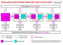
May give you some hints for explanation, but do not disclose too much. I use a self-developed technique to perform system modeling of home audio system, just for fun as an audio amateur. My job does not relate to audio industry and this technique does not apply to home audio before personally as well as you cannot find it in any textbook.
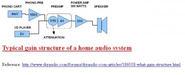
Just talk about high level conceptual design, but not detail design such as calculation of CMMR, resistor, OPAMP, etc… First of all, you need to know the concept of “fully balanced design” and “differential amplifier”. I do not explain again as you can find it in many standard documents. The main difference between balanced (XLR) and unbalanced (RCA) transmission are:
1) Single channel balanced (XLR) carries 2-way and 3 cores (+V, -V, GND) while unbalanced (RCA) carries 1-way and 2 cores (+V, GND). Hence, the material used in fully balanced system will be double to unbalanced system.
2) There is no way to completely filter out the noise in unbalanced transmission while differential amplifier can be used to filter out the noise in balanced transmission with theoretically zero noise level.
3) The basic design goal of balanced design is to maintain same noise immunity to both positive and negative single channel analog signal transmission, thus use differential amplifier to filter out all the noise. In order to achieve this goal, the minimum requirement is:
=>The positive and negative analog signal transmission should be mirror symmetry (such as ultra symmetry said by Pass Labs) with equal signal path (same noise immunity to positive and negative signal path), but not necessary to be the shortest signal path (it is good as it can be).
=>The electronic components between positive and negative (left and right for stereo) must be fully matched within target tolerance, say 0.1%.
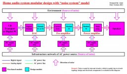
4) The principle of “precedence rule” and the concept of “system dynamic”.
=>HiFi system basically follows the principle of “precedence rule”. The sound quality of receiver depends on the sender (e.g. power amplifier follows the pre-amplifier). Hence, noise input to receiver depends on the noise from sender plus environmental interference in static signal system.
=>The concept of “system dynamic”. You should note that the differential amplifier is put at the junction between static signal system and dynamic signal system. A static system is also called signal non-amplification system and there is no voltage gain in term of gain concept. A dynamic system is also called signal amplification system and voltage gain exists within this system.
=>The application of differential amplifier behaves different to both static signal system and dynamic signal system. The source of noise is:
=>Noise of static signal system = noise from sender + noise from environmental interference
=>Noise of dynamic signal system = noise from sender + noise from environmental interference + circuit topology (main amplification unit + power supply), etc..
=>Noise in dynamic signal system is more complex than static signal system
=>Differential amplifier is an effective tool to filter out noise in static system with theoretical zero noise level. But, it is more complex in dynamic signal system which is subject to the assumption in achieving the goal in the design of circuit topology for both main amplification and power supply module.
Lastly, the noise above refers to analog signal processing while the digital noise refers to concept of “jitter”, another headache problem. I cannot guarantee that you understand, but I try my best effort to explain. No more in detail!
Hope it help!
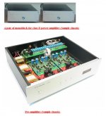
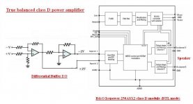
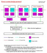
My new design is coming. It consists of a true balanced OPAMP pre-amplifier and a pair of monoblock class D power amplifier, both with differential buffer I/O added. Spend 5~10% of time in development, thus no rush!
Design goal
1) It is a low cost and very simple design, but with true balanced design in compatible to high price audio amplifier.
2) The total budget cost is less than USD 1,500 for both pre-amplifier and power amplifier.
3) It is suitable audio DIY beginner for easily installation which is based on modular design and “plug and play” concept.
4) The sound is clear with very low distortion (THD+N) at around 0.003% for pre-amplifier (based OPAMP used) and 0.03% for power amplifier (based on class D module used).
5) It is based on the concept of “noise free” for silent background with differential buffer I/O added. In my concept, true balanced design means balanced design with differential amplifier added. For balanced design without differential amplifier, the sound quality is similar to unbalanced design with double circuitry unless there is another method to filter the noise.
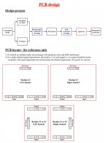
Pre-amplifier
1) It is an OPAMP based with 3 stages amplification: Buffer input + Main amplification + Buffer output (similar to MBL6010D, but not copying)
2) The total voltage gain = 4 x (1 + R2/R1). For standard 10x pre-amplification, the ratio of R2/R1=1.5.
3) The signal path is free of decoupling capacitor to give a very clear sound. Decoupling capacitor is not a must, but signal path with and without decoupling capacitor behaves two different sounds which is subject to individual preference.
4) Bypass capacitor is used in the regulated voltage supply rail to filter the noise from DC power source. If the voltage supply is unregulated, a shunt regulator should be used to provide precision voltage supply.
5) Other accessories such as input selector, attenuator, front display, chassis, etc… can be purchased from standard DIY kit set.
Power amplifier
1) It is a pair of monoblock with buffer input and main amplification from class D module in bridged mode (BTL mode)
2) The power output is 500W/8Ω per channel
3) It is based on the “plug and play” concept for easily installation.
Recommendation for better sound
1) The discrete component of transistor based class A circuit (I/V stage) is regarded as the best sound from most of experienced audio Diyers. For this reason, the main amplification unit of pre-amplifier can be changed from OPAMP based circuit to transistor based discrete class A under modular design.
2) If you dislike the clear sound, but want sweet and soft taste of sound, you may add decoupling capacitor in the signal path of pre-amplifier.
3) The reason to select B&O Icepower class D module is the best c/p value at low cost. For better sound, go to Hypex UcD or NewClassD as well as Class AB amplifier. (Ref: http://www.diyaudio.com/forums/class-d/185709-enquiry-about-diy-class-d-power-amplifier.html )
Design goal
1) It is a low cost and very simple design, but with true balanced design in compatible to high price audio amplifier.
2) The total budget cost is less than USD 1,500 for both pre-amplifier and power amplifier.
3) It is suitable audio DIY beginner for easily installation which is based on modular design and “plug and play” concept.
4) The sound is clear with very low distortion (THD+N) at around 0.003% for pre-amplifier (based OPAMP used) and 0.03% for power amplifier (based on class D module used).
5) It is based on the concept of “noise free” for silent background with differential buffer I/O added. In my concept, true balanced design means balanced design with differential amplifier added. For balanced design without differential amplifier, the sound quality is similar to unbalanced design with double circuitry unless there is another method to filter the noise.
Pre-amplifier
1) It is an OPAMP based with 3 stages amplification: Buffer input + Main amplification + Buffer output (similar to MBL6010D, but not copying)
2) The total voltage gain = 4 x (1 + R2/R1). For standard 10x pre-amplification, the ratio of R2/R1=1.5.
3) The signal path is free of decoupling capacitor to give a very clear sound. Decoupling capacitor is not a must, but signal path with and without decoupling capacitor behaves two different sounds which is subject to individual preference.
4) Bypass capacitor is used in the regulated voltage supply rail to filter the noise from DC power source. If the voltage supply is unregulated, a shunt regulator should be used to provide precision voltage supply.
5) Other accessories such as input selector, attenuator, front display, chassis, etc… can be purchased from standard DIY kit set.
Power amplifier
1) It is a pair of monoblock with buffer input and main amplification from class D module in bridged mode (BTL mode)
2) The power output is 500W/8Ω per channel
3) It is based on the “plug and play” concept for easily installation.
Recommendation for better sound
1) The discrete component of transistor based class A circuit (I/V stage) is regarded as the best sound from most of experienced audio Diyers. For this reason, the main amplification unit of pre-amplifier can be changed from OPAMP based circuit to transistor based discrete class A under modular design.
2) If you dislike the clear sound, but want sweet and soft taste of sound, you may add decoupling capacitor in the signal path of pre-amplifier.
3) The reason to select B&O Icepower class D module is the best c/p value at low cost. For better sound, go to Hypex UcD or NewClassD as well as Class AB amplifier. (Ref: http://www.diyaudio.com/forums/class-d/185709-enquiry-about-diy-class-d-power-amplifier.html )
Attachments
For reference purpose, the budget cost is based on the following list of material (To be confirmed). There are some choices of purchased parts as below:
Resistor
1) PRP PR9372 (0.1% tolerance) – USA
2) Philips MPR24 (0.1% tolerance) – Netherland
Capacitor (DC voltage supply bypass)
1) WIMA MKP2, 5% Metallized Polypropylene – Germany
2) ELNA Silmic II, 20% Electrolytic capacitor – Japan
OPAMP
1) TI/ National Semiconductor: Dual LM4562 or Single LME49710/LME49713 - USA
2) TI/ Burr Brown: Dual OPA2604 or Single OPA604 - USA
PSU voltage regulator (Dual and single voltage regulator)
1) Walt Jung super voltage regulator – USA
2) Golden reference UCC voltage regulator – Taiwan
Transformer
1) Plitron toroid transformer – Canada
2) Multicomp toroid transformer – USA
Digital module
1) Buffalo II DAC module (based on the ESS Sabre32 Reference, ES9018) – USA
Power amplifier module (Output power 500W x2/8Ω)
1) B&O Icepower 250ASX2 class D module – Denmark
2) International Rectifier IRS2092 class D module + SMPS – USA
3) National Semiconductor LME49810 + BJT class AB module – USA
4) National Semiconductor LME49830 + Mosfet class AB module – USA
Attachments
Hi,
if You insist on ease and low complexity, why don´t You simply use dedicated ICs such as the Balanced Line Drivers DRV134 (BB/TI) or SSM2142 (ADI) and the associated Balanced Line Receivers INA134/INA137 (BB/TI) or SSM2141 (ADI). Combining Gain and differential outputs take a look at the AD8432.
Anyway, as Conrad already pointed out the differential systems advantage is its immunity against contaminated environment and long distance signal transmission. At home this is usually not the case, so there´s no real advantage going symmetric but it costs effort. Noise isn´t an issue with highlevel audio signals and using at least a bit of design-sense (or following app-notes).
I find it a bit amusing about Your negative talk about caps on one hand, but using OPs and class-D amplification on the other. Believe it or not, but a good coupling cap las much less negative effect on sonics than ICs or class-D.
A last point. Why don´t You follow the proven recommendations regarding supply line decoupling and use good quality ceramic caps together with electrolytics instead of a Wima film cap? A film cap is no good idea here, inferior in suitability, costly and large sized.
A bit funny, but Your design goals and the proposed solution don´t really match. E.g. a ´simple´ Preamp design is hardly a 3-stage design, but a single stage design. You could easily put gain stage and output buffer into one stage.
Keeping the signal path free of caps either allows any DC at the input to appear amplified at the output (added the stages own offset, especially at power on/off). Adding a DC-Servo on the other hand puts caps and additional active stages into the signal path again.
At the moment Your ideas read a bit like a collection of hyped items but not necessarily like a ist of good design.
jauu
Calvin
Hi,
if You insist on ease and low complexity.
jauu
Calvin
Dear Calvin,
Formally, few people are qualified to speak to me directly. I just say politely that thank you for your comments and I have no time to review anymore. I can see many good designs in this Diyaudio forum. For hobbyist, just make own design stuff and share with Diyers. Please don’t mind if it is correct or wrong. If wrong, just discard it while right for reference only. Children play toys, but audio DIY is adult’s toys.
Recently, I have just created a temporary homepage to capture all the captioned information for audio DIY experience sharing. If you are interested, feel free to visit my personal homepage for DIY audio at New Page 1 .
- Status
- Not open for further replies.
- Home
- Amplifiers
- Solid State
- My new design of differential buffer I/O board for fully balanced design