a1greatdane:
Thank you for your post there is some nice info there. I'm not sure if you've been monitoring this thread since the beginning, but if you have you will understand that the LTP input was a brief tangent that we went on for a few posts but ultimately decided against. We stuck with the SE input for simplicity and favourable distortion characteristics.
In any case I now have this thing stable, biased at 1A and sounding simply terrific. .
(though I'm yet to seriously test into capacitive loads, but at least it's fine just sitting there now)
I can not believe the sound. It is toasty warm with nicest resonating bass you have ever heard. You can really hear the second harmonic....I'm sure it would measure terribly.
Thanks lineup for stimulating my interest in this topology.
I would have to say that its only weak point with my current configuration is a lack of treble, but I'm yet to try my better speakers so that may prove to be incorrect.
As was commented earlier, with the square wave performance this amplifier has poor treble would be unexpected.
I will post the current working schematic soon.
Last edited:
Hi swordfishy,
good news - I can't wait to build mine.
this is the best I came up with so far using a .22 ohm o/p res but in my experience bought o/p resistors often sound dreadful therefore my 0.22 ohm resistor would be a small length of "constantan" resistance wire which would double as an o/p fuse which I will need because mine will be DC linked - the 5nF after the 0.22 res in an essential part of the design.
if all that sounds too complicated probably a 1uH choke with 1ohm in parallel will also work - but I did not try that with this exact arrangement
you can see I did my compensation from the VAS - this was the best arrangement I tried - at least in spice - this was a JLH technique.
adding any miller cap made things worse
the BJT hawksford cascode helped with stability
but if your's sound great already then perhaps just enjoy it")
mike
good news - I can't wait to build mine.
this is the best I came up with so far using a .22 ohm o/p res but in my experience bought o/p resistors often sound dreadful therefore my 0.22 ohm resistor would be a small length of "constantan" resistance wire which would double as an o/p fuse which I will need because mine will be DC linked - the 5nF after the 0.22 res in an essential part of the design.
if all that sounds too complicated probably a 1uH choke with 1ohm in parallel will also work - but I did not try that with this exact arrangement
you can see I did my compensation from the VAS - this was the best arrangement I tried - at least in spice - this was a JLH technique.
adding any miller cap made things worse
the BJT hawksford cascode helped with stability
but if your's sound great already then perhaps just enjoy it
mike
Attachments
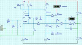


The working circuit
Mikelm,
Your circuit looks good. Do you think you'll be building it any time soon? I want to hear what you think of it. Is the output choke really necessary? I quite like the vas comp too.
Dansky, thanks for the schematic. What is it about the sound you think is missing? Your construction is much neater than mine. Looks good!
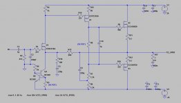
This is my current circuit which appears stable. I'm not sure how to test capacitive loads exactly, but I put a 1uF cap directly across the output and tried square and sine waves from 0 - 20kHz and low and high power. No apparent problems, just a little ringing on the square wave test. Is that useful info?
Currently the overall gain is quite low, and it will take the full 2V RMS from a typical CD player to get anywhere near clipping. This suits me fine as it saves me having to use an attenuator except for very low volume listening.
The thing that really made the difference was increasing the feedback and sacrificing some CLG. The OLG is still not too bad though - only 100R and 60R degen resistors for the input and VAS stages respectively. I tried a lot of OLG/CLG combos and this is the first one that worked. It seems very stable now, and I am unable to entice it in to oscillating by tapping the input or components with my finger, etc.
Mikelm,
Your circuit looks good. Do you think you'll be building it any time soon? I want to hear what you think of it. Is the output choke really necessary? I quite like the vas comp too.
Dansky, thanks for the schematic. What is it about the sound you think is missing? Your construction is much neater than mine. Looks good!
This is my current circuit which appears stable. I'm not sure how to test capacitive loads exactly, but I put a 1uF cap directly across the output and tried square and sine waves from 0 - 20kHz and low and high power. No apparent problems, just a little ringing on the square wave test. Is that useful info?
Currently the overall gain is quite low, and it will take the full 2V RMS from a typical CD player to get anywhere near clipping. This suits me fine as it saves me having to use an attenuator except for very low volume listening.
The thing that really made the difference was increasing the feedback and sacrificing some CLG. The OLG is still not too bad though - only 100R and 60R degen resistors for the input and VAS stages respectively. I tried a lot of OLG/CLG combos and this is the first one that worked. It seems very stable now, and I am unable to entice it in to oscillating by tapping the input or components with my finger, etc.
Attachments
Last edited:
DF
Hi mikelm,
You realise that this 0.22 ohm output resistor gives a max damping factor of 36 and with the low open loop gain it could be even lower...This looks more like tube amp...
Fab
...this is the best I came up with so far using a .22 ohm o/p res ...)
mike
Hi mikelm,
You realise that this 0.22 ohm output resistor gives a max damping factor of 36 and with the low open loop gain it could be even lower...This looks more like tube amp...
Fab
Dansky, thanks for the schematic. What is it about the sound you think is missing?
Probably dominant H3 because i am grown up with it, MC Tape Walkman, and i never had a Turntable.
Last edited:
damping factor
Yeah, I'm aware of that, I did it consciously because both John Curl & John Linsley Hood have observed that amps sound better without an o/p choke.
Also I mostly expect to have a separate amp to do the low bass which is really the only range that really need a high damping factor and even then
many people are of the opinion that a DF of 25 - 50 would be just fine.
Nelson Pass has concluded long ago that high damping factor does not necessarilly sound good.
Now swordfishy has demonstrated that this amp seems to be stable with just an o/p zobel / snubber or whatever we call that cap & res at the o/p, so the option seems to be there to have a high DF . . . . . . .
. . . . . . but I suspect that I would still prefer a lower DF but I have to say that most resistors in this position, in my experience often totally ruin the sound of an amp so I would choose this component very carefully indeed as I detailed above but also perhaps a good non-inductive wire wound would be good.
I cannot build yet - I just moved back from USA to UK and all my audio stuff has still to be shipped
Last edited:
Probably dominant H3 because i am grown up with it, MC Tape Walkman, and i never had a Turntable.
Yeah, I think you're right. Sometimes I think it lacks "detail" and "definition" but then I listen carefully and realise it's all in there, just a little more "integrated" than I'm used to. The final version especially has shown a vast improvement in definition, i think partially due to the addition of the 1uf cap across the bias resistor. What kind of music are you listening to?
We both have pretty different amplifiers really. The only similarity at this point is that we both have fet output stages and a SE input so I wonder how they might compare sound wise. I will add the jfet input when they arrive, though I am reluctant to mess with an already good thing. Fortunately the pinouts are the same.
Another thing, when I finally got rid of the oscillation I heard a distinct improvement in the sound. Whether this was due to the removal of the oscillation itself, or the circuit changes made to remove the oscillation, I don't know.
Oh, one more thing you might like to try. The cap across the bias resistor made an audible difference for me. My previous simulations demonstrated that the cap reduces distortion at high frequencies and I'm fairly sure I could hear that....
Anyway, it's certainly better than a lot of others I have heard, and the trouble shooting and development process has been a real buzz.
Mikelm,
I would not be too concerned about the bass performance. In fact I think bass is one of this amplifier's real strengths.
The only thing I'm yet to ascertain for sure is whether the dc offset is stable enough. It seems fine while not connected to speakers then you attach some equipment and it changes. Need more time to investigate this.
Ultimately a servo may be required, as was mentioned previously.
Thanks for your support during this process.
The final version especially has shown a vast improvement in definition, i think partially due to the addition of the 1uf cap across the bias resistor. What kind of music are you listening to?
Oh, one more thing you might like to try. The cap across the bias resistor made an audible difference for me. My previous simulations demonstrated that the cap reduces distortion at high frequencies and I'm fairly sure I could hear that....
I wanted to ask you, what results do you have in your sims when you increase the 1uF capacitor, in terms of distortion?
Another thing, try to decrease the gate stopper resistors, not in sims, but in your current assembly, and listen, how much does bass change on this?
Can you upload the sim file along with the models?
I started to think that I should assemble mine and try it out myself, too, tomorrow will see if I can get all the components in one go from local shops.
Thanks
What kind of music are you listening to?
Hip-hop Blues Soul, thats my Corner preferable Acoustic.
At the moment Alicia Keys Unplugged, all her Albums are really great sounding Records.
Yeah i will try the suck-out C in the next Days.
danspy, metal,
It seems I have told a white lie about the suckout capacitor. When I was trying different things in simulation it did have a positive effect on HF distortion when used with a BJT VAS with a miller cap, but with the current uncompensated FET VAS it actually makes things worse.
Funny, because I still maintain that I like the sound more with it in place...
My apologies for misleading you. I have simmed so many circuits in the last week or so that they have all blurred together, and I assumed that the benefit would apply to any VAS.
That said, it is still worth trying danspy as you do indeed have a BJT VAS.
Last edited:
Metal,
Here are the figures. It would seem that the sucker cap helps at 2kHz and is detrimental at 20kHz. Note these figures are at about 22v p-p output. Seems it would be worth using one in that case as I can't even hear 20kHz. Maybe there's a measurable reason for why l prefer the sound with it in after all.
2kHz with sucker cap:
Fourier components of V(to_spkr)
DC component:0.0138852
Harmonic Frequency Fourier Normalized Phase Normalized
Number [Hz] Component Component [degree] Phase [deg]
1 2.000e+03 1.077e+01 1.000e+00 0.26° 0.00°
2 4.000e+03 1.171e-03 1.087e-04 -99.77° -100.02°
3 6.000e+03 1.723e-03 1.599e-04 3.53° 3.28°
4 8.000e+03 5.715e-04 5.306e-05 86.34° 86.09°
5 1.000e+04 4.196e-04 3.896e-05 -178.06° -178.32°
6 1.200e+04 2.265e-04 2.103e-05 -90.46° -90.71°
7 1.400e+04 1.429e-04 1.327e-05 -0.68° -0.94°
8 1.600e+04 7.802e-05 7.244e-06 86.67° 86.41°
9 1.800e+04 3.862e-05 3.586e-06 178.45° 178.19°
Total Harmonic Distortion: 0.020595%
2kHz without sucker cap:
Fourier components of V(to_spkr)
DC component:0.0145908
Harmonic Frequency Fourier Normalized Phase Normalized
Number [Hz] Component Component [degree] Phase [deg]
1 2.000e+03 1.077e+01 1.000e+00 0.27° 0.00°
2 4.000e+03 2.753e-03 2.555e-04 -87.40° -87.66°
3 6.000e+03 2.442e-03 2.267e-04 5.93° 5.67°
4 8.000e+03 1.128e-03 1.047e-04 97.18° 96.92°
5 1.000e+04 6.313e-04 5.859e-05 -169.94° -170.21°
6 1.200e+04 2.522e-04 2.341e-05 -77.84° -78.11°
7 1.400e+04 3.497e-05 3.246e-06 10.23° 9.97°
8 1.600e+04 8.356e-05 7.756e-06 -72.68° -72.95°
9 1.800e+04 1.246e-04 1.156e-05 17.52° 17.25°
Total Harmonic Distortion: 0.036304%
20kHz with sucker cap:
Fourier components of V(to_spkr)
DC component:0.0132126
Harmonic Frequency Fourier Normalized Phase Normalized
Number [Hz] Component Component [degree] Phase [deg]
1 2.000e+04 1.071e+01 1.000e+00 -0.10° 0.00°
2 4.000e+04 1.061e-03 9.904e-05 -105.91° -105.81°
3 6.000e+04 2.070e-03 1.932e-04 46.34° 46.45°
4 8.000e+04 5.842e-04 5.452e-05 143.10° 143.20°
5 1.000e+05 5.539e-04 5.170e-05 -112.98° -112.88°
6 1.200e+05 3.031e-04 2.829e-05 -22.04° -21.93°
7 1.400e+05 1.686e-04 1.574e-05 73.58° 73.68°
8 1.600e+05 8.860e-05 8.269e-06 -170.81° -170.71°
9 1.800e+05 7.558e-05 7.054e-06 -79.16° -79.06°
Total Harmonic Distortion: 0.023223%
20kHz without sucker cap:
Fourier components of V(to_spkr)
DC component:0.0127333
Harmonic Frequency Fourier Normalized Phase Normalized
Number [Hz] Component Component [degree] Phase [deg]
1 2.000e+04 1.072e+01 1.000e+00 -0.09° 0.00°
2 4.000e+04 3.822e-04 3.565e-05 -0.16° -0.06°
3 6.000e+04 1.582e-03 1.475e-04 78.07° 78.17°
4 8.000e+04 3.238e-04 3.020e-05 -170.82° -170.73°
5 1.000e+05 2.356e-04 2.197e-05 150.60° 150.69°
6 1.200e+05 5.721e-04 5.335e-05 -145.37° -145.28°
7 1.400e+05 5.804e-04 5.413e-05 -64.54° -64.45°
8 1.600e+05 3.747e-04 3.495e-05 -9.06° -8.97°
9 1.800e+05 5.225e-04 4.874e-05 7.96° 8.05°
Total Harmonic Distortion: 0.018387%
Last edited:
- Status
- This old topic is closed. If you want to reopen this topic, contact a moderator using the "Report Post" button.
- Home
- Amplifiers
- Solid State
- JFET input, MOSFET VAS, LATERAL output = Perfect!!