Hi everyone, i was just wondering if anyone had implemented a power amplifier in the style of the Aleph series but used bipolar output transistors rather than mosfets? Having posted on shaans thread recently this idea suddenly occured to me. Ok so i know it's not a Pass clone, but there are similarities that gave me food for thought ")
I'm pretty well swamped with mosfets but thought about the fact that bipolars have a much higher transconductance than mosfets. I also happen to have quite a few MJ11016 N channel darlingtons that could easily be put to use
These would be more than suitable on something like a +/- 24V supply to keep them well in the SOA.
Ok, so they won't be as fast as mosfets, but higher transconductance should lead to better linearity with low feedback i'd have thought...
Any thoughts on the subject? Thanks in advance...
Mods, if this is in the wrong area feel free to move it. I didn't want to post it in the Passlabs section as it's simply a query
Have a look at the SOA graph for your darlington, also at the Ft. As you say, +-24V would just about be as far as you can push it.
That being said, like Zen Mod says, if you wanted to do this with bipolars only, you would need at least a buffer stage after or before the LTP, because of current demand issues.
You could use a 'hybrid' approach, with a MOSFET input like in the original. Input capacitance notwithstanding (this is really the only truly problematic thing in that amp), it's relatively easy to get driving current from MOSFETs if you can get rid of the heat - you just increase the tail current. Added gm and in many cases better linearity (depends on the MOSFET chosen, if you wish you can always use a bit of degeneration given added tail current and keep the same gm at better linearity) are always a plus.
Last edited:
I was thinking all bipolar. I don't have a problem with fairly high currents through the LTP & yes i was still thinking of a buffer to drive the base of the lower darlingtons & another single transistor emitter follower to drive the upper set.
I'd obviously be paralleling a few up just to make sure i keep them on the safe side, i realise they are close to the edge with a decent current @ these voltages. Well, not the 24V but when approaching the rails might be problematic..
I just fancy something a little different.
Cheers for your input ilimzn
Any thoughts on the subject? Thanks in advance...
I have had the same thoughts, but my reason is that i prefer the sound of BJTs especially on the HF.
I think that I can post here instead of opening a new thread.
The following is what i have in mind.
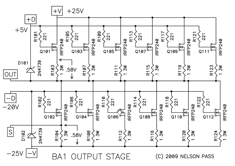
The circuit on which I want to base my design is the BA-1:
Yes, the bipolars needs stronger drivers and probably predrivers too (= more stages). The frontend may well include jfets and mosfets.
Low beta droop fast transistors for output devices and VERY fast drivers, such as Sanken's 2SA1859/2SC4883.
Opinions are welcome.
I was thinking all bipolar. I don't have a problem with fairly high currents through the LTP & yes i was still thinking of a buffer to drive the base of the lower darlingtons & another single transistor emitter follower to drive the upper set.
I'd obviously be paralleling a few up just to make sure i keep them on the safe side, i realise they are close to the edge with a decent current @ these voltages. Well, not the 24V but when approaching the rails might be problematic..
I just fancy something a little different.
Cheers for your input ilimzn
Increasing the input tail current with bipolars offers advantages of higher gm, or more linearity if degeneration is used (and I would strongly recomend that it IS used), but it also increases base current, which in turn increases noise current and thus noise, unless you want to make the input impedance quite low. Of course, noise current is not a linear function of base current but in general with typical transistors we'd be talking about here, we are talking about a few mA. With MOSFETs you could just as well use 100mA and except for gm and heat, not much would change (even though MOSFETs also have optimum Id for lowest noise, but again, with types in question here, it's something they were never characterized for, so it can vary quite a lot depending on the actual type and manufacturer).
I think that the classical approach of a relatively small (compared to MOSFETs) tail current and a follower after the LTP would be the way to go. Using followers in front of the LTP may end up still needing a follower after, only because of the limitation of BJTs to use in a high current LTP not being that easy to find.
Still, I don't see why it wouldn't be doable...
Hi Telstar, you are more than welcome on here chapI have had the same thoughts, but my reason is that i prefer the sound of BJTs especially on the HF.
I think that I can post here instead of opening a new thread.
I intend to add an Aleph type output stage with bipolars simply to reduce the quiescent current a bit. I can't exactly say whether i prefer mosfets or bipolars for outputs simply because i have only ever heard only one mosfet amp (that i know of) in my whole life I'll be using something like BC560C transistors on the LTP & yes i'll be using fairly heavy emitter degeneration. I'm not too worried about a low input impedance so i can certainly use a low value resistor for feedback & on the ground resistor on the input. Some messing with a bootstrap capacitor as per Doug Self could be used to increase AC input impedance, though i'm not sure i'll bother. I'd even consider paralleling a few transistors (with seperate degeneration resistors) if tail current became an issue. Though on a few amps i designed previously a 5mA tail current wasn't a problem.. It's all up in the air right now & this isn't the most important project that i'm working towardsIncreasing the input tail current with bipolars offers advantages of higher gm, or more linearity if degeneration is used (and I would strongly recomend that it IS used), but it also increases base current, which in turn increases noise current and thus noise, unless you want to make the input impedance quite low. Of course, noise current is not a linear function of base current but in general with typical transistors we'd be talking about here, we are talking about a few mA. With MOSFETs you could just as well use 100mA and except for gm and heat, not much would change (even though MOSFETs also have optimum Id for lowest noise, but again, with types in question here, it's something they were never characterized for, so it can vary quite a lot depending on the actual type and manufacturer).
I think that the classical approach of a relatively small (compared to MOSFETs) tail current and a follower after the LTP would be the way to go. Using followers in front of the LTP may end up still needing a follower after, only because of the limitation of BJTs to use in a high current LTP not being that easy to find.
Still, I don't see why it wouldn't be doable...
I do have an idea of how i'm going to go about this & i'll endevour to get up some kind of circuit diagram as soon as possible. I'd draw it with LTspice if & when i suss out exactly how to use the thing properly
I can't seem to get the thing to put PNP transistor into a circuit the correct way up 
So it might be a scrawl on a bit of paper.
Again, thanks for showing an interest guys - much appreciated!
I'm commited now...
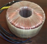
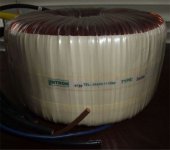
Well it looks like this project is definately going to go ahead as i have commited myself by buying a couple of toroidal transformers
I was going to use a load of 0 - 18V frame types to generate +/- 24V but that was a tad too close to the 25V caps i have floating about here (47,000uf cans). Instead i found some odd toroids that are dual 0 - 17V at supposedly 1KVA yet the specs don't fit. These things are 165 x 90mm & weigh in at 9.5Kg each, looking at Airlink Transformers site it would appear they could well be 1.5KVA each
So i think a pair of balanced monoblocs are going to be built...
We shall see I'll be back
Well it looks like this project is definately going to go ahead as i have commited myself by buying a couple of toroidal transformers
I was going to use a load of 0 - 18V frame types to generate +/- 24V but that was a tad too close to the 25V caps i have floating about here (47,000uf cans). Instead i found some odd toroids that are dual 0 - 17V at supposedly 1KVA yet the specs don't fit. These things are 165 x 90mm & weigh in at 9.5Kg each, looking at Airlink Transformers site it would appear they could well be 1.5KVA each
So i think a pair of balanced monoblocs are going to be built...
We shall see
I'll be back I love ebay
We have transformers Brand new pair delivered for £60.
Had to do a little research on these beasts. They look to be using the same size core as the 1.5KVA transformers made by Airlink, but checking up on Lintrons' site they are definately 1KVA. Interesting that the regulation is better than the Airlink 1KVA & the same as their 1.5KVA toroidals. These things have been over-engineered The wire exiting the toroid is 6mm^2 on the secondaries, again, over-engineered & they measure bang on the money at 17.5V AC, which with 3% regulation will be 17V at full load - just what i wanted.
Well i'm sure they'll each cope with a 100W RMS (8ohm) monoblock
We have transformers
Brand new pair delivered for £60.Had to do a little research on these beasts. They look to be using the same size core as the 1.5KVA transformers made by Airlink, but checking up on Lintrons' site they are definately 1KVA. Interesting that the regulation is better than the Airlink 1KVA & the same as their 1.5KVA toroidals. These things have been over-engineered
The wire exiting the toroid is 6mm^2 on the secondaries, again, over-engineered & they measure bang on the money at 17.5V AC, which with 3% regulation will be 17V at full load - just what i wanted.Well i'm sure they'll each cope with a 100W RMS (8ohm) monoblock
Attachments
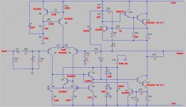
Having sussed out how to turn a PNP transitor the right way round (with LTspice) i knocked up a provisional circuit diagram of the kind of thing i intend to build.
I'm not going to simulate this amp in any way, i have never simulated anything in my life. Besides that i doubt very much that there are equivalents for either the BUP41, SM2178 (both Semelab) or MJ11016 (i could be wrong on the latter but i doubt it).
This amp (when finished) will be a bridge amplifier which should be capable of near on 28V RMS into 8 ohm, 4 ohm won't give it a problem with the power supply it'll be having so i might just see 200W RMS into 4 ohms. PSU will be somewhere in the order of 100 - 150,000UF per rail, i just need to take stock of the capacitors.
I'm not going to nuts with the quiescent current, i reckon that 1.5A per amplifier should be more than enough, so that would be 3A quiescent per bridge amp for a total power dissipation of about 150W per monoblock with no signal. The idea behind this is that the amp can turn on much more current if it needs it. I might see what happens with a higher quiescent but these are only going to be driving an old pair of Celestion Ditton 66 monitors. In fact the speakers could do with a total rebuild (they had no idea about non resonant cabinets back in the day).
Lots of parts in the circuit diagram will need to be established empirically, hense the ??? The circuit may well alter slightly, i have already realised where things might not be as i intended.
The inverting channel will be taken off of the base of the input transistor of this amp & the current mirror reversed on the LTP so the second amp inverts. No rocket science there then
No idea how long this will take, i have a whole house to run single handedly & i'm not in the best of physical heath. I'm sure i'll get there in the end though
I'm not going to simulate this amp in any way, i have never simulated anything in my life. Besides that i doubt very much that there are equivalents for either the BUP41, SM2178 (both Semelab) or MJ11016 (i could be wrong on the latter but i doubt it).
This amp (when finished) will be a bridge amplifier which should be capable of near on 28V RMS into 8 ohm, 4 ohm won't give it a problem with the power supply it'll be having so i might just see 200W RMS into 4 ohms. PSU will be somewhere in the order of 100 - 150,000UF per rail, i just need to take stock of the capacitors.
I'm not going to nuts with the quiescent current, i reckon that 1.5A per amplifier should be more than enough, so that would be 3A quiescent per bridge amp for a total power dissipation of about 150W per monoblock with no signal. The idea behind this is that the amp can turn on much more current if it needs it. I might see what happens with a higher quiescent but these are only going to be driving an old pair of Celestion Ditton 66 monitors. In fact the speakers could do with a total rebuild (they had no idea about non resonant cabinets back in the day
).Lots of parts in the circuit diagram will need to be established empirically, hense the ??? The circuit may well alter slightly, i have already realised where things might not be as i intended.
The inverting channel will be taken off of the base of the input transistor of this amp & the current mirror reversed on the LTP so the second amp inverts. No rocket science there then
No idea how long this will take, i have a whole house to run single handedly & i'm not in the best of physical heath. I'm sure i'll get there in the end though
Attachments
I see two possible problems with your approach.
First is that the choice of bias current is not arbitrary. The current source used has internal positive feedback to make it more 'active' but it still poses a limit to what you can drive in the positive output voltage direction. Actually, simulation may well be in order here, using complex loads (it's all going to seem very nice using a resistor as a load, and speakers are not).
Second, reversing the input diffamp conenction also requires you to reverse where the NFB comes in (or it will not be NFB), so you are back to where you started - in order to make it inverting, it will have to use inverting op-amp connection.
Hi, i have had a few beers so allow me time to digest thisI see two possible problems with your approach.
First is that the choice of bias current is not arbitrary. The current source used has internal positive feedback to make it more 'active' but it still poses a limit to what you can drive in the positive output voltage direction. Actually, simulation may well be in order here, using complex loads (it's all going to seem very nice using a resistor as a load, and speakers are not).
Second, reversing the input diffamp conenction also requires you to reverse where the NFB comes in (or it will not be NFB), so you are back to where you started - in order to make it inverting, it will have to use inverting op-amp connection.
Well the MJ11016 is a 200W device with a 200C temp limit. I intend to use either 4 or 6 per amplifier which would be either 8 or 12 devices per complete bridge amplifier. Yes, i reckon it's enough to make the thing near bomb proofHello Event ,
Do you believe the 4 output devices are enuff for that power output ?
That's a minimum of 1600W of transistors, though i'm more likely to go for 12 which would be 2.4KW of devices. I think that'll be ok Yep, bang on... I need to drink less having thought about itSecond, reversing the input diffamp conenction also requires you to reverse where the NFB comes in (or it will not be NFB), so you are back to where you started - in order to make it inverting, it will have to use inverting op-amp connection.
re: pass style power amp with bipolars?
why not nelson's own 20 watt class a power amp from audio magazine 1977? the pdf is posted on one of the pass sites somewhere. single ended, all bipolar, true class a. in spite of the age of the design, likely still a very fine amp in it's own right. impressive measurements, scope shots and "how does it sound" comments, all in one article. and who knows what would happen with modern parts and a tweak here or there?
although i haven't done it yet (probably never will the way things are going these days), this was actually the reason i acquired a bunch of the MJ21194 and MJ21193 parts a while ago.
mlloyd1
ok, i found the link:
http://www.passdiy.com/pdf/classa_amp.pdf
Last edited:
why not nelson's own 20 watt class a power amp from audio magazine 1977? the pdf is posted on one of the pass sites somewhere. single ended, all bipolar, true class a. in spite of the age of the design, likely still a very fine amp in it's own right. impressive measurements, scope shots and "how does it sound" comments, all in one article. and who knows what would happen with modern parts and a tweak here or there?
although i haven't done it yet (probably never will the way things are going these days), this was actually the reason i acquired a bunch of the MJ21194 and MJ21193 parts a while ago.
mlloyd1
ok, i found the link:
http://www.passdiy.com/pdf/classa_amp.pdf
Great memory lane trip, there used to be some great articles coming out of Audio during that era ........

Last edited:
Actually that's not really much of a problem with the way Mr Pass has designed his Aleph type output stages. Must admit they are quite ingenious, which is what made me think of using this type. The whole output stage could be biased to full class A fairly simply, it's just a question of selecting the correct resistors for certain positions. I happen to have quite a few MJ11016 toAnotehr advantage of BJT is you dont need a second HT to counteract the high gate voltage of MOSFET's.
I have found I needed upto 7 volts bias to get the MOSFETs out of crossover distortion.
I like the simplicity of a differential amp & the fact that you don't need to mess about to get a really low offset voltage & thus avoid an output capacitor.Why VFB? Wny not CFB?
Cheers for the linkwhy not nelson's own 20 watt class a power amp from audio magazine 1977? the pdf is posted on one of the pass sites somewhere. single ended, all bipolar, true class a. in spite of the age of the design, likely still a very fine amp in it's own right. impressive measurements, scope shots and "how does it sound" comments, all in one article. and who knows what would happen with modern parts and a tweak here or there?
although i haven't done it yet (probably never will the way things are going these days), this was actually the reason i acquired a bunch of the MJ21194 and MJ21193 parts a while ago.
mlloyd1
As it happens i have seen it previously, interesting artical & what looks like pretty decent performance to say the least.Why not he asks? Well i like to DIY
Ok, so i might have swiped the output stage but that's about as far as it goes. It certainly won't end up quite the same as that initial circuit as i already have some slight modifications in mind (it never stops  ).
).I might see if i can get something going on a breadboard in the near future, only the output transistors will really need an major heatsinking so i'll be able to test out my ideas.
Thanks for popping in everyone
Bests, Mark.
- Status
- This old topic is closed. If you want to reopen this topic, contact a moderator using the "Report Post" button.
- Home
- Amplifiers
- Solid State
- Has anyone implemented a Pass style power amp with bipolars?