Hi
After some speaker posts.
http://www.diyaudio.com/forums/showthread.php?t=130857&highlight=helmuth
http://www.diyaudio.com/forums/showthread.php?t=137036&highlight=helmuth
I have a nice vintage solid state project!
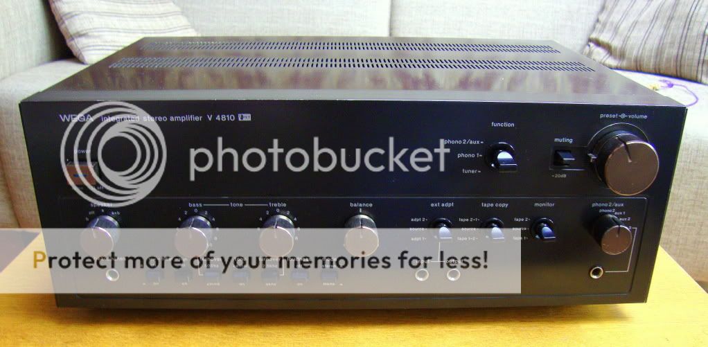
To be more precise I wanted a nice vintage set because they look so good. What is more attractive as an vintage amp then one with a J-fet preamp and V-fet end stage.
A V-fet is on the solid-state area the best match to a Triode Tube. When you look to the amplifying characteristics. So the damping factor of a solid state and sound of a tube.
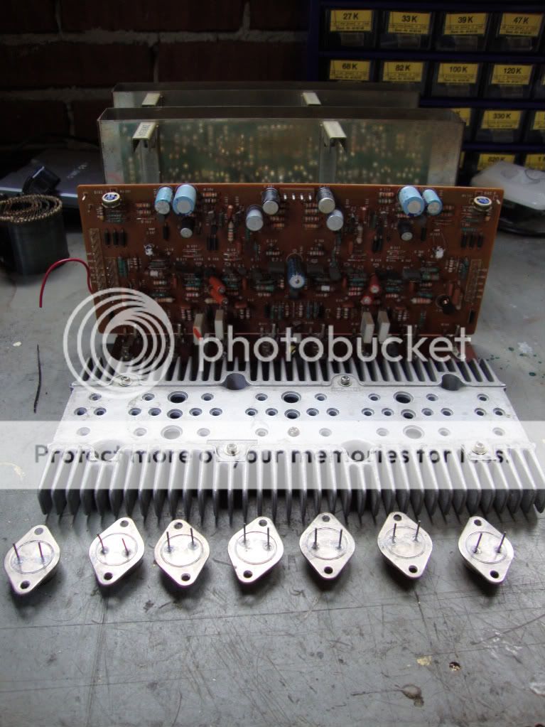
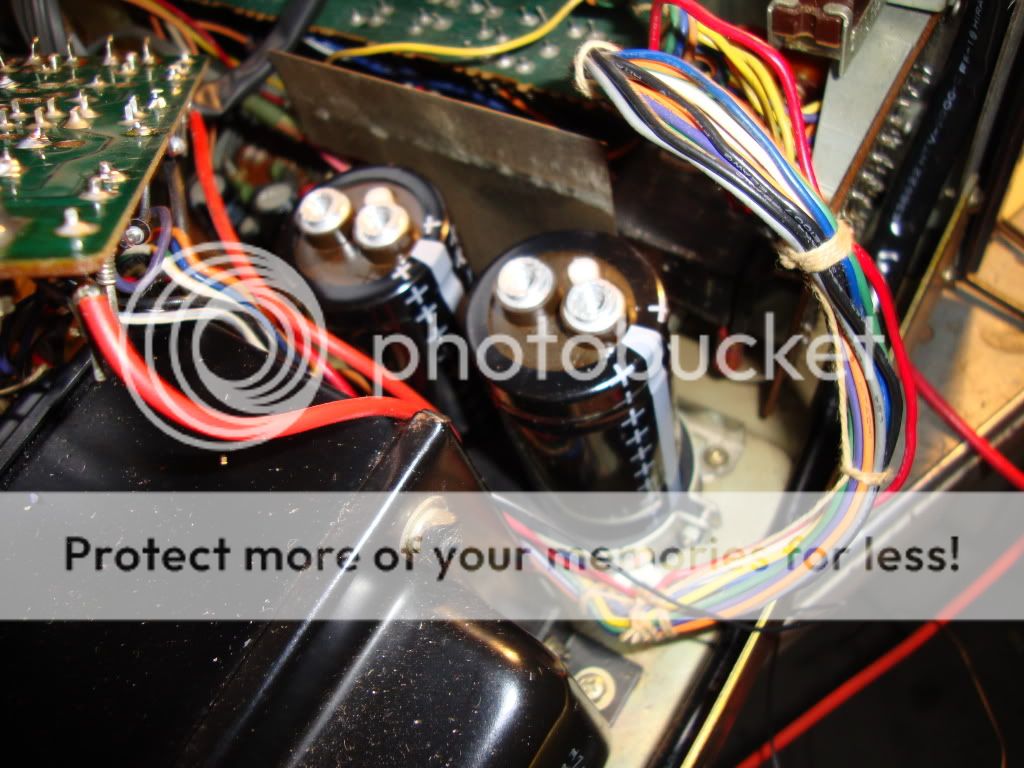
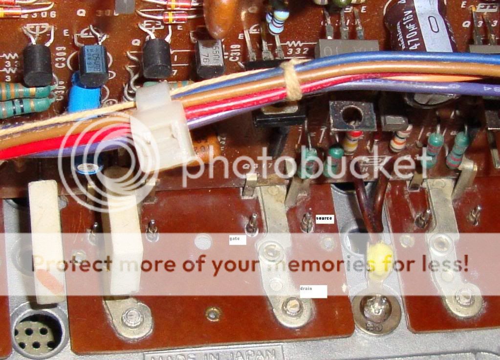
All V-fets are defect are defective except one 2sk60. Picture of the endstage and defect V-fets.
Regards, Helmuth
After some speaker posts.
http://www.diyaudio.com/forums/showthread.php?t=130857&highlight=helmuth
http://www.diyaudio.com/forums/showthread.php?t=137036&highlight=helmuth
I have a nice vintage solid state project!
To be more precise I wanted a nice vintage set because they look so good. What is more attractive as an vintage amp then one with a J-fet preamp and V-fet end stage.
A V-fet is on the solid-state area the best match to a Triode Tube. When you look to the amplifying characteristics. So the damping factor of a solid state and sound of a tube.
All V-fets are defect are defective except one 2sk60.
Picture of the endstage and defect V-fets.Regards, Helmuth
Last edited:
This amplifier is really beautifull..congratulations.... i hope you fix it
Despite your amplifier has a very good look, the yellow motorcicle looks even better!
regards,
Carlos
Despite your amplifier has a very good look, the yellow motorcicle looks even better!
regards,
Carlos
Attachments

Last edited:
Despite your amplifier has a very good look, the yellow motorcicle looks even better!
regards,
Carlos
Investegating my photo's carlos
 😀
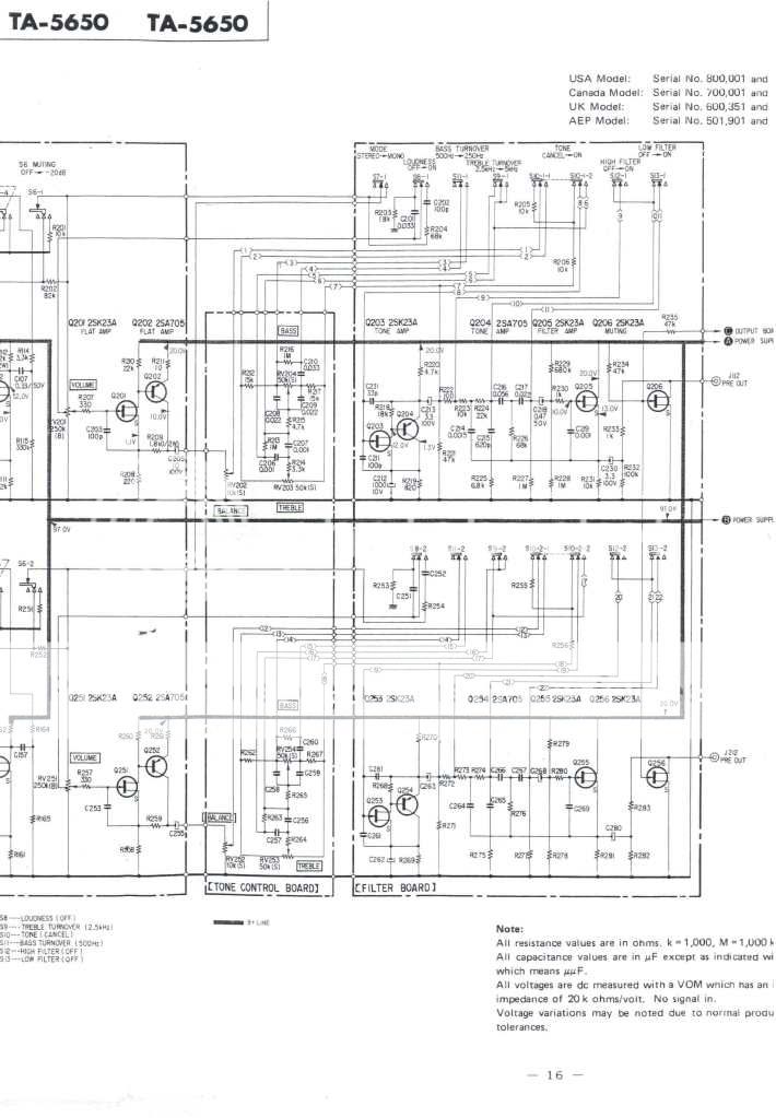
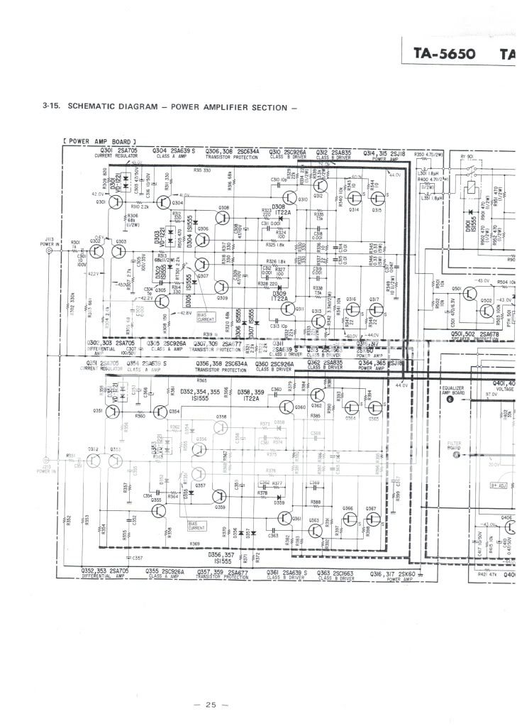
😀I downloaded a unreadable schematic at http://www.hifiengine.com/manuals/sony/ta-5650.shtml
after that I got a readable one from Jerry.
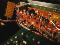
Low noise J-fet preamp in combination with bipolar:
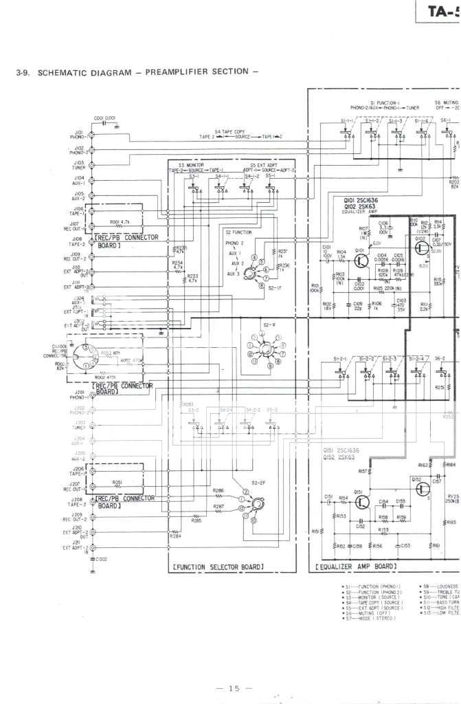
cheers Helmuth
Last edited:
A white paper on mods on the V-fet amp I found on karma. It is from the belgium service cennter of Sony. Very important the lower bias-current to prevent a temperature avalanche effect.
I introduced the mods on my amp.
I introduced the mods on my amp.
An externally hosted image should be here but it was not working when we last tested it.
Last edited:
Hi guys
The end stage was unsuccessfully repaired, may be more then one attempt, that I could see.
The result all V-fets defective except 1 2sk60. You can do a diode test to see it is defective. So open without negative gate voltage the V-fet measures as a short. Most of the transistors where not original ones any more.
I tried to become them by brokers but they won't sell part below a quantity of 50 pieces or more.
So I searched for alternatives for my self. And use common European alternatives. It seemed to me that in America it is easier to find Japanese transistors.
I replaced the missing:
2SA705 by BC560B the european low noise type PNP.
2sc634a by BC546B
2sa677 by BC556B
2sa639s by 2SB648A a nice toshiba alternative also obsolete
2sc926a by 2SD668A a nice toshiba alternative also obsolete
I also replaced al capacitors by new ones. Electrolithic capasitors dry out inside after a long period. This affect increases by high environment temperature. So the capasitors of the endstage will be faster worn then the ones on the preamp board.
I advise to replace them by 105 degrees types they are designed to have long lifetime at high temperature.
They have high voltage types in the design to prevent leakage current and sound and losses produced by this current. So today capacitors are smaller you can even choose types with even higher voltage rating.
I will replace some capacitors by Wima MKS types. They have lower absorbent losses then eletrolithic capacitors, almost as good as a MKP capacitor only much smaller. So they fit in the place of the old electrolithic types. And their have an almost unlimited live expectancy.
http://www.wima.de/EN/WIMA_MKS_2.pdf
The proportionality constant relating each material's capacitance enhancement over that of a vacuum is known as its "dielectric constant."
In A.C. applications, where signal handling is involved, factors which affect the rates of both charging/discharging become key issues. Even though dielectrics with larger constants allow smaller size/capacitance devices, the properties of such dielectrics contribute deleteriously to audio signal processing.
The residual charge from dielectric relaxation is known as the "dielectric absorption." When an audio signal is passed through a capacitor the dielectric absorption prevents full charging and discharging of the capacitor at the frequency of the alternating current signal. When the signal reverses the charging on the plates the dielectric absorption presents a lagging current of the former polarity, a hysteresis effect results. This effect becomes more acute with increasing frequency.
Obviously now, not all dielectrics are equal. In audio applications it is desirable to seek the insulating material with the lowest practical dielectric absorption; hence, lowest dielectric constant, barring size and economics. Dielectric materials can be classified based on their relative polarity/polarizability properties, which the dielectric constants and dielectric absorptivities parallel.
What follows is a qualitative categorization of dielectric materials in decreasing polarity/polarizability based on chemical structure considerations (Dielectric constant data "K" given when available):
I. Metal oxide corrosion layers (electrolytic capacitors):
1) Tantalum oxide (K = 11)
2) Aluminum oxide (K = 7)
Both consist of polar metal oxide bonds possessing large permanent dipole moments, polarizability factors are negligible.
II. Ceramics and Glasses:
1) Ceramics - typically alumina or aluminosilicates (K = 4.5 - thousands)
2) Glasses - typically borosilicate (K = 4-8.5)
Similarly, the polar inorganic oxide bonds in these materials have large permanent dipole moments.
III. Minerals:
1) Mica (most common) - an alkali metal aluminosilicate, hydrate (K = 6.5 - 8.7)
Same as II.
IV.
A. Polymer films - functionally linked - ranked in order of decreasing functional linkage polarity (brackets "[ ]" indicate guess based on functional group polarity):
1) Polyesters (ex. Mylar) - ester (K = 3.2 - 4.3)
2) [Kapton - ether and imide]
3) Polyamides (ex. Nylon) - amide (K = 3.14 -3.75)
4) Polycarbonate - carbonate (K = 2.9)
5) [PEEK - ether and ketone]
6) [Poly(phenylene oxide) - PPO - ether]
7) [Poly(phenylene sulfide) - PPS- thioether]
The members of the above list can essentially be ranked based on polarity considerations alone, though polarizability considerations are significant for the latter members of the list.
B. Polymer films - carbon chain backbone - ranked in order of decreasing attached-group polarity/polarizability:
1) Poly(vinyl chloride) - PVC - chloro-substituted (K = 3.3 - 4.55)
2) Poly(chlorotrifluoroethylene) - chloro- and fluoro-substituted (K = 2.48 - 2.76)
3) Poly(p-phenyleneethylene) - Parylene - exception to list phenyl ring in backbone (K = 2.65)
4) Polystyrene - phenyl-substituted (K = 2.54 - 2.56)
5) Polyethylene - essentially unsubstituted carbon chain (K = 2.3 - 2.37)
6) Polypropylene - methyl-substituted (K = 2.1)
7) Poly(tetrafluoroethylene) (ex. Teflon) - perfluoro-substituted (K = 2.0 - 2.1)
So how lower the K factor the lower the absorbsion losses.
MKS is polyester = K3.4-4.3
Cheers Helmuth
Last edited:
I am listening to the amp right nowI would be very surprised if you will find any V-FETs.🙄

Before I bought it I first checked if I could buy new V-fets of course.
Regards
Last edited:
I bought the NOS V_FET's in Hongkong quite a risky job but it turned out to be OK.
First step in testing and rebuilding the endstage.
Step 1
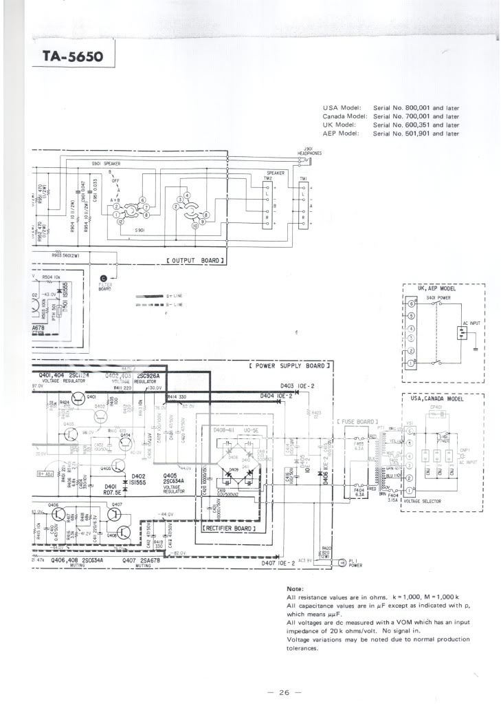
Test of the power supply.
Remove all connectors of the endstage board.
Switch on the power. On the front plate in the right coner there is a powersupply board with one potentiometer to adjust the +20 Volt. The +97 volt shout also be automatic the right value.
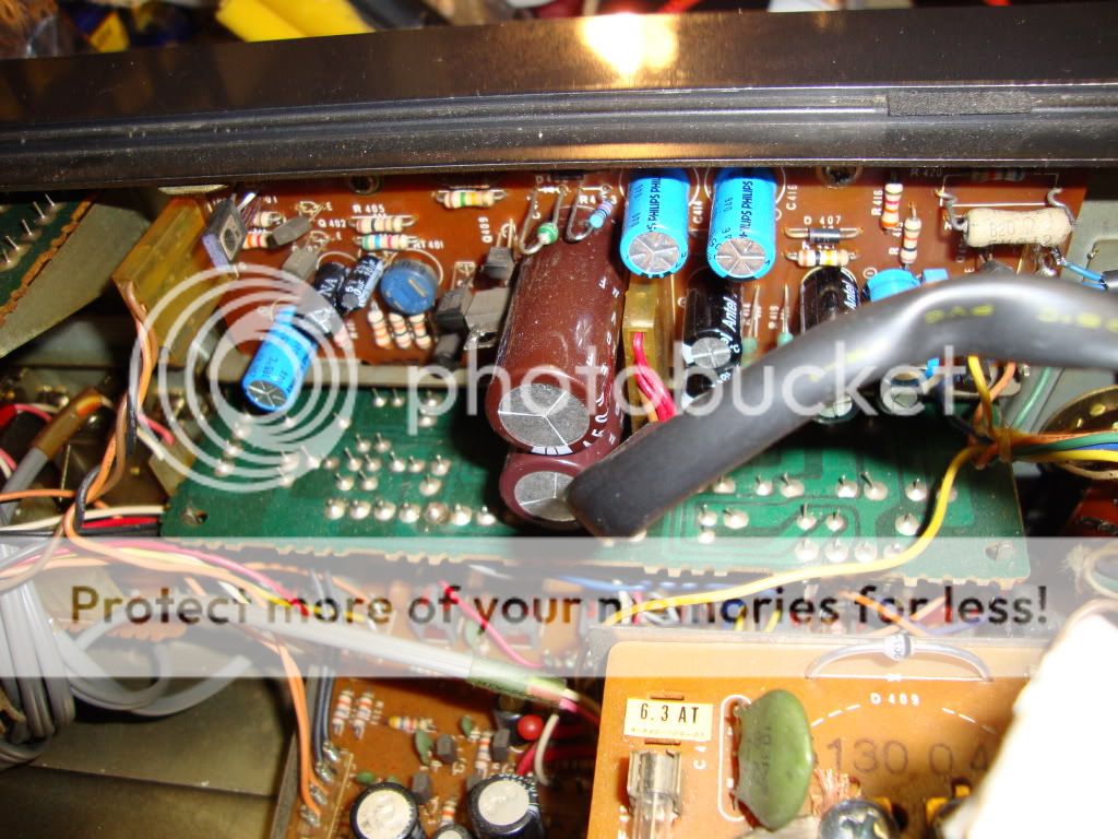
Over R419 an R414 we must see about + and - 90Volt. Then also over the big capacitors the main powersuplly voltage - and + 45Volt.
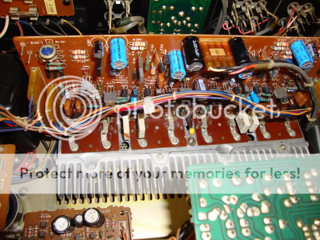
The new EPCOS caps 10000uF 63V
New caps and transistors on the endstage.
Regards, Helmuth
First step in testing and rebuilding the endstage.
Step 1
Test of the power supply.
Remove all connectors of the endstage board.
Switch on the power. On the front plate in the right coner there is a powersupply board with one potentiometer to adjust the +20 Volt. The +97 volt shout also be automatic the right value.
Over R419 an R414 we must see about + and - 90Volt. Then also over the big capacitors the main powersuplly voltage - and + 45Volt.
The new EPCOS caps 10000uF 63V
New caps and transistors on the endstage.
Regards, Helmuth
After step1 testing the voltages the 20V and 97V where OK.
But the +/- 90V and +/-45V where not symmetrical distributed and started slowly to drift.
I could not under stand what was going on??
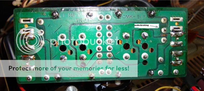
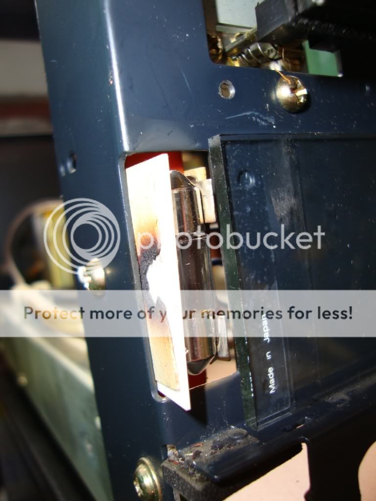
Then I discovered the problem why the previous owner couldn't fix the amplifier and blew it over and over again. The was a open in the circuit board of the rectifier.
Probably caused by short of defective V-fets and switching on the amp with new fuses. The open was from the junction of the to power capacitors to the ground junction of the two secondary.
Look here to see the open it is the bottom of the circuit board.
I hope I did other service Mann a favour here by posting this cause.
Regards and keep them running Helmuth
But the +/- 90V and +/-45V where not symmetrical distributed and started slowly to drift.
I could not under stand what was going on??
Then I discovered the problem why the previous owner couldn't fix the amplifier and blew it over and over again. The was a open in the circuit board of the rectifier.
Probably caused by short of defective V-fets and switching on the amp with new fuses. The open was from the junction of the to power capacitors to the ground junction of the two secondary.
Look here to see the open it is the bottom of the circuit board.
I hope I did other service Mann a favour here by posting this cause.
Regards and keep them running Helmuth
When step 1 is succesfull. so the 20V ,97V, +/-90V and +/-45V are OK we can go to the next step.
Step 2
We can test the end-stage with out V-fets attached to it. The driver stage of the V-fet amp is capable to drive the headphone output.
By this test we can see the if the pre-end-stage is working properly with out blowing the precious V-fets.
I attach the input connector of the preamp on the end-stage board and the power-supply connector of the left-channel.
Now you can check only the left stage voltages. I switch the preamp to phono 1 and use my finger to introduce hum to the left cinch connector of phono 1.
When this works properly you can also connect the power-supply of the right channel to the end stage. End test the voltages and listen if it amplifies normal. I did use my finger to make input noise, you can also connect a cd-player to the amp as source and listen music through the headphone output.
I made a custom made tool to clean the connector leads. It is a old monkey-wrench ( I do not know this is the right name) it is harden steel. It is cut in a triangle shape to scrape the surface of the leads of the connector.
I also cleaned TO3 foot for the V-fet it was polluted with coolant pasta. It would be a catastrophe when the gate would not make contact with the fitting. I also measured the contact resistance after fitting a V-Fet to it, before switching on the new fets.
The tool.
After finishing step 2 we can move to the last step and test with the V-fet.
Step 3
To prevent the fets from a possible dead, Piet told me he used resistors in series with the main voltage.
I thought a while, power resistors are expensive. Then I had a idea to use lamp bulbs as power resistor. I bought two Philips 500W halogen lamps for 8 Euro.
The behaviour of a light bulb is like a PTC the resistance can increase 10 times after glowing up. In this case the lamp had a resistance of 7.5Ohm in cold state. And when I shorted the 45+45 Volt with the two lamps in series the current was about 900mA.
Perfect to protect the V-fet.
I used a small piece off MDF and a angled aluminium profile and 12 wood screws to fit the lamps. A nice advantage was that the profile worked like a spring when I screw the lamp between it.
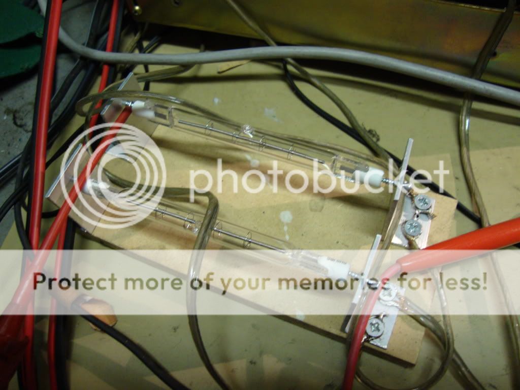
To start I only fit 1 2sj18 and 1 2sk60 on the left channel to start with.
Then I bais the circuit to 25mV, test the voltage and listen to it.
*note when de potentiometer is in the left corner it is at his minimum value, the 25mV is measured over one 0.33Ohm resistor at the output.
Then I fit the second one on the left channel. Then I bais the left channel to 50mV.
If this works well I repeat this procedure for the right channel.
After fitting all 8 V-fets it was possible to listen to music on the connected speakers, YESS it worked. My occupation is electronics and i have repaired many switching power supplies in my career till now. But it was a bit a gamble to buy this amp and try to buy Nos V-fets in china find replacement transistors. It could turnout in a disaster and loose the investment.
You know what happens when your wife finds out.
Regards, Helmuth
Step 3
To prevent the fets from a possible dead, Piet told me he used resistors in series with the main voltage.
I thought a while, power resistors are expensive. Then I had a idea to use lamp bulbs as power resistor. I bought two Philips 500W halogen lamps for 8 Euro.
The behaviour of a light bulb is like a PTC the resistance can increase 10 times after glowing up. In this case the lamp had a resistance of 7.5Ohm in cold state. And when I shorted the 45+45 Volt with the two lamps in series the current was about 900mA.
Perfect to protect the V-fet.
I used a small piece off MDF and a angled aluminium profile and 12 wood screws to fit the lamps. A nice advantage was that the profile worked like a spring when I screw the lamp between it.
To start I only fit 1 2sj18 and 1 2sk60 on the left channel to start with.
Then I bais the circuit to 25mV, test the voltage and listen to it.
*note when de potentiometer is in the left corner it is at his minimum value, the 25mV is measured over one 0.33Ohm resistor at the output.
Then I fit the second one on the left channel. Then I bais the left channel to 50mV.
If this works well I repeat this procedure for the right channel.
After fitting all 8 V-fets it was possible to listen to music on the connected speakers, YESS it worked. My occupation is electronics and i have repaired many switching power supplies in my career till now. But it was a bit a gamble to buy this amp and try to buy Nos V-fets in china find replacement transistors. It could turnout in a disaster and loose the investment.
You know what happens when your wife finds out.
Regards, Helmuth
Here a picture of the leads to disconnect so you can put a lamp in series with it.
One lamp in series with the brown wire, and one in series with the violet wire.
(There is also a third violet wire, connected to speaker protection do not disconnect that one other wise the speaker protection switches on.)
The halogen lamp trick works with every end stage repair.

Helmuth wishes you success with repairing.
One lamp in series with the brown wire, and one in series with the violet wire.
(There is also a third violet wire, connected to speaker protection do not disconnect that one other wise the speaker protection switches on.)
The halogen lamp trick works with every end stage repair.
Helmuth wishes you success with repairing.
After fixing the endstage there was a bop noise and a little hum on the left channel.
After switching the prestage left en right on the back. I could find out that it was the prestage right channel who caused the problem.
I hoped after replacing al capacitors the amp would sound right. This was not the case so there was something broken.
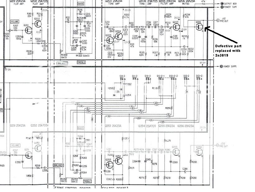
I began checking the voltages of the preamp seemed ok, after switching on with the last stage of the preamp the bop still was not gone. So my eye fell on the mute FET , (Q206, Q256) Q206 acted as a resistor. I replaced them both with the 2n3819 it is only a switch, and saved the intact 2sk23a as a spare for later.
http://www.datasheetcatalog.org/datasheet/vishay/70238.pdf
new list
2SA705 by BC560B the european low noise type PNP.
2sc634a by BC546B
2sa677 by BC556B
2sa639s by 2SB648A a nice toshiba alternative also obsolete
2sc926a by 2SD668A a nice toshiba alternative also obsolete
2sk23a by 2n3819 a good replacement for the mute fets not tested in the amplifier part.
Now the amp is working and sounding fine and warm.
Regards Helmuth
After switching the prestage left en right on the back. I could find out that it was the prestage right channel who caused the problem.
I hoped after replacing al capacitors the amp would sound right. This was not the case so there was something broken.
I began checking the voltages of the preamp seemed ok, after switching on with the last stage of the preamp the bop still was not gone. So my eye fell on the mute FET , (Q206, Q256) Q206 acted as a resistor. I replaced them both with the 2n3819 it is only a switch, and saved the intact 2sk23a as a spare for later.
http://www.datasheetcatalog.org/datasheet/vishay/70238.pdf
new list
2SA705 by BC560B the european low noise type PNP.
2sc634a by BC546B
2sa677 by BC556B
2sa639s by 2SB648A a nice toshiba alternative also obsolete
2sc926a by 2SD668A a nice toshiba alternative also obsolete
2sk23a by 2n3819 a good replacement for the mute fets not tested in the amplifier part.
Now the amp is working and sounding fine and warm.
Regards Helmuth
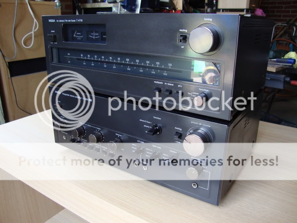
The Tuner had a Little Service.
The light bulbs where broken and I made hardwood side panelsfor the wega set.
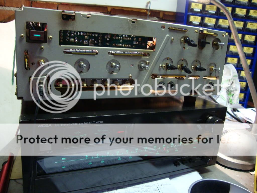

The light bulbs are available at every car parsts shop because they also fit Japanese cars.
Regards Helmuth
The light bulbs where broken and I made hardwood side panelsfor the wega set.
The light bulbs are available at every car parsts shop because they also fit Japanese cars.
Regards Helmuth
The V-fet is fully conducting current when there is no negative gate voltage. So in this design it is important to check that path to keep the amp healthy.
There is a lot said about the double diodes.
There are more threats to the V-fet than the doublediode's,
1)The bias potentiometer when the middle contact of the potentiometer fails to make contact=disaster.
I advise a 1K 10 turn potentiometer to replace the 2k5 one turn. You will have a smooth adjusting pot.
And you have to let the amp to heat up at normal ambient temperature adjust to the right BIAS.
2)The connectors are a weak point the +76V when they fail to make contact= disaster.
Like one previous poster you can skip the connectors and make a sturdy wire wrap connection.
3)Also the gate has to make contact with the fitting when ONE fails disaster. So clean the contact and make sure with a resistance measurement that it makes contact.
Regards, Helmuth
The set is playing for a while now. Low frequency like a tube amp and a high response without harshness. Nice sound.
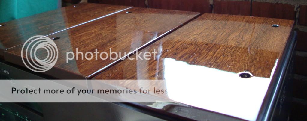
I made some pictures with my home made Bankirai side panels.
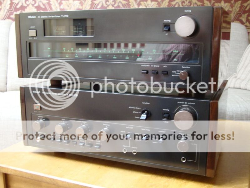
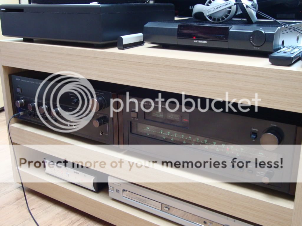
Regards Helmuth
I made some pictures with my home made Bankirai side panels.
Regards Helmuth
Hey Hemuth, that looks like a job well done! I hope your amps are sounding well now... It seems they do ;-)
I especially like the good craftsmanship on the wooden side panels. How did you get the high gloss and keeping the dust away while the paint dries? I always get small specs of dust when trying to do a high-gloss paint job.
I especially like the good craftsmanship on the wooden side panels. How did you get the high gloss and keeping the dust away while the paint dries? I always get small specs of dust when trying to do a high-gloss paint job.
- Status
- Not open for further replies.
- Home
- Amplifiers
- Solid State
- V-fet Repair of a WEGA V4810 solid state heaven