Funky....
a couple of thoughts;
Now I know this is "diyAudio" and DIYing can be fun, but I suggest that you stop working on getting this QED working. Not because it can't be done. You need to educate yourself on basic electronics, so you have a(at least) a very basic understanding of electricity and electronics. The transformer can push enough current that you can be seriously injured or worse (' ').
').
If this was a "find" it will wait until you learn a little and maybe have tackled some basic projects on your own, or through evening "interest" classes at your local community centre or college or high school.
I am not trying to be overly critical, it is just that based on some of your questions, you simply have a non-existent understanding of this. You really need to take some time and learn some skills. It really is for your own safety I am making these comments. It is not personal, nor am I attacking your "intelligence". What I am suggesting is that it seems you are already "over your head". I would hate to find out that somehow you were injured working on this.
So put the QED away for now, and take a course, buy a good book on basic electronics (Radio Shack or Tandy used to have a really basic, but informative book for only a few $$), and gain a little confidence. If you need the amp fixed now, get it into a repair shop.
I'd still encourage you to take a course, regardless. Once you learn skills, nothing (except perhaps age...) can take that away form you.
stew
a couple of thoughts;
- if you are having this much trouble identifying basic parts, you should stop
- sreten made a suggestion to disconnect the transformer output from the amp, but you don't really understand things, so you are asking very basic questions, so you should stop and "re-group"
- because you don't understand the basics you could seriously injure yourself--please stop working on this NOW!
Now I know this is "diyAudio" and DIYing can be fun, but I suggest that you stop working on getting this QED working. Not because it can't be done. You need to educate yourself on basic electronics, so you have a(at least) a very basic understanding of electricity and electronics. The transformer can push enough current that you can be seriously injured or worse ('
').If this was a "find" it will wait until you learn a little and maybe have tackled some basic projects on your own, or through evening "interest" classes at your local community centre or college or high school.
I am not trying to be overly critical, it is just that based on some of your questions, you simply have a non-existent understanding of this. You really need to take some time and learn some skills. It really is for your own safety I am making these comments. It is not personal, nor am I attacking your "intelligence". What I am suggesting is that it seems you are already "over your head". I would hate to find out that somehow you were injured working on this.
So put the QED away for now, and take a course, buy a good book on basic electronics (Radio Shack or Tandy used to have a really basic, but informative book for only a few $$), and gain a little confidence. If you need the amp fixed now, get it into a repair shop.
I'd still encourage you to take a course, regardless. Once you learn skills, nothing (except perhaps age...) can take that away form you.
stew
I am not going to work on this amp on my own. I am very interested in amplification and am trying to learn about it. I do understand that electronics can be dangerous which is why I am working with a friend who knows what he is doing. I am just trying to learn as much about it as I can before I see him next week to test the transistors with a multimeter. If the transistors come up as fine I will try again to take it to a repair shop.
Funky....ok, cool.
I just would really hate to see you get injured ...
If your friend is experienced, then I'm sure in person he can help you , and you'll end up learning. The Tandy book, if still available, is almost as basic as it can get. A bonus was that it was really cheap to buy.
I hope I didn't come across as condescending, I really wanted to underline the safety issues.
stew
thanks, i appreciate your concern. From experience with computers I have learned that it is important to know what I am doing before I try it and would not want to do anything too complicated until I am sure what I am about to do is right which is why I am getting in person help with this. I have also been researching into testing transistors for my own interest.
lohk... you are right, they are triple darlingtons. The first stage uses BC546 (BC556) , the Second stage BD140 (BD139) and finally, the Third Stage BD911 (BD912).
Funky971... Nanook raises some very good points about working with potentially lethal mains voltages present. I'm glad to note you are working with someone knowledgable and are using this opportunity to learn about amplifiers and transistors.
Good luck and let us know how it goes!
Funky971... Nanook raises some very good points about working with potentially lethal mains voltages present. I'm glad to note you are working with someone knowledgable and are using this opportunity to learn about amplifiers and transistors.
Good luck and let us know how it goes!
Thank you Funky.
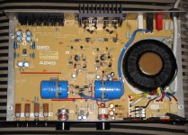
Lot's of changes between version 1 and version 2 are evident in the layout and features but not in the speaker connections. You'll need to look for narrow profile 4mm banana plugs and just make sure they don't short each other out when plugged it. (Version 1 has output fuses visible in the back-right portion - just below the power cable, while version 2 lacks them).
But before you get to that stage you'll need to sort out the blowing fuses first. What fuses did you replace them with? (The markings on my board lists them as "1.6A Anti-surge" for a 220-240V mains voltage).
Assuming that the blowing fuse is of the correct rating, I'd try to rule out a shorted transformer by disconnecting the secondary windings from the board (the two yellow and two white wires), powering it up with a new fuse and see if it blows again. (If it does, you've got a shorted transformer which needs replacement). If it doesn't then the next place to look is at your output devices (as already mentioned by others here).
Ok, thanks, the fuse in mine is the 1.6 amp antisurge. When I was trying to get the amp fixed I took it to two shops. The first one was more of a PA shop than a hifi shop. They opened up the amp and tried a new fuse however they did not have the exact one (I think it needed a T type fuse and they put an F type in instead). They put a different rating in because they said it would compensate for it being the different type. That one blew so he checked the wiring of the plug and tried another one which also blew. He then realized it was a hifi amp and told me to go to the second place which wouldn't even look at it. I am going to go to maplin this week and get some of the correct fuses.
Hi,
To check the transformer you can remove the bridge rectifier.
The supply is difficult to isolate from the power amplifier, but
there are standard multimeter checks for shorted capacitors
and a shorted bridge rectifier, though the probable cause is
as I've said a short output transistor. Test everything in
situ with no power before trying any powered tests.
http://en.wikipedia.org/wiki/Multimeter
http://www.repairfaq.org/sam/semitest.htm#stttm
http://www.repairfaq.org/REPAIR/F_tshoot.html
") /sreten.
/sreten.
To check the transformer you can remove the bridge rectifier.
The supply is difficult to isolate from the power amplifier, but
there are standard multimeter checks for shorted capacitors
and a shorted bridge rectifier, though the probable cause is
as I've said a short output transistor. Test everything in
situ with no power before trying any powered tests.
http://en.wikipedia.org/wiki/Multimeter
http://www.repairfaq.org/sam/semitest.htm#stttm
http://www.repairfaq.org/REPAIR/F_tshoot.html
/sreten.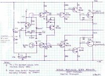
ok, just a quick amp update
Me and my friend opened up the amp today and had a look, as suspected the BD911 on the left channel has shorted out. Because they are so cheap and it is a lot of effort to take the board off to take the transistor off we are going to replace all four output transistors. He also ran some multimeter checks on the transformer which came out ok.
Me and my friend opened up the amp today and had a look, as suspected the BD911 on the left channel has shorted out. Because they are so cheap and it is a lot of effort to take the board off to take the transistor off we are going to replace all four output transistors. He also ran some multimeter checks on the transformer which came out ok.
I've got one of these to repair the main output transistors are BD711 / BD712 I can't get these so I'm thinking BD911/912? these OK?
the 4 resistors are R47 all seem to be damaged, but the right channel seems to be more burned probably by shorting the speaker wire?
the main output transistors are BD711 / BD712 I can't get these so I'm thinking BD911/912? these OK? the 4 resistors are R47 all seem to be damaged, but the right channel seems to be more burned probably by shorting the speaker wire?
Attachments
Mine's the slightly bigger, newer version with dials for input selectors instead of push buttons. Mine does have BD911 and BD912 for it's output transistors. As far as I know the amps are the same under the bonnet but I'm not entirely sure.
I'm pretty sure that mine blew by shorting out the speaker lead and there was no sign of burning inside like the picture you posted.
If you get it working it's a nice amp though!
Let us know how you get on.
Edit: Just realised I didn't report back after fixing - it was a while after posting this that we got it fixed but it was rude of me not to come back and let you know how I got on. For those interested we got it working after replacing the power transistors. It's a nice amp and I still use it now.
Last edited:
dynoPort - Yes you can use BD911/912 as alternatives. The design of the speaker out jacks are a recipe for short circuits! Good luck on your repair and let us know how it goes.
Funky971 - No worries mate. Appreciated the update. Yes it's a wonderful little amp. I'm still using mine too
Funky971 - No worries mate. Appreciated the update. Yes it's a wonderful little amp. I'm still using mine too
Huge thanks to this forum - and Leslie in particular...
Hi,
Thanks to finding this forum and for Leslie's help in particular, I have been able to reinstate the stable working of my A240CD amp.
Lately, I've noticed that it's been running very warm indeed (and getting warm very quickly) - not good for a long and stable life. I was also worried that if the output transistors went into thermal runaway, they might take my much loved Wharfedale 504 speakers with them.
Armed with the schematics for the series 2 version of this amp, I was able to locate the points for measuring the bias voltages on my series 1, and from the service information, I knew that the bias voltage should be approx 15mV - it says 15mV on one page in the service document and 10-20mV on another page.
When I measured my amp - the bias on one channel was at about 30mV, and on the other it was about 50mV. Yikes! No wonder it was getting warm.
With some very careful and gradual adjustments of the bias potentiometers, I was able to get the bias to about 16mV on each channel. Not bad.
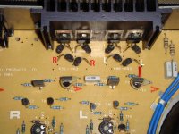
In the spirit of sharing information to help future enquirers, I thought I'd post up images of where the bias voltages should be measured from, and the bias potentiometers to adjust the voltages.
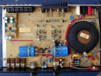
The first photo is just a general shot of the interior of the amp. Note on this one, no output fuses. I love the very simple, logical layout of these amps: very clean - like the sound.
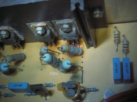
The points to measure the bias voltages from are marked R (right channel) and L (left channel) in the photo below - connect your voltmeter between R and R for the right channel and L and L for the left channel.
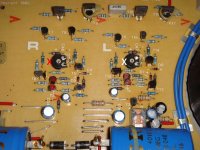
The bias potentiometers are marked with red (right) and white (left) X's on the photo below that. On my amp, turning them counterclockwise reduces the bias voltage. Beware - they are VERY sensitive!
After making the adjustments and leaving the amp to settle for a further few minutes and then re-checking the bias voltages (still fine), I closed up the case and put the amp back into my system. It might have been my imagination, but I'll swear it sounded more "relaxed" and less stressed than before. It was definitely running much cooler - after a couple of hours of use, it was much cooler than it would have been after perhaps 5 or 10 minutes of listening prior to making the adjustments.
I know I felt more relaxed and less stressed in the knowledge that my amp was once more operating as it had been designed to.
Hi,
Thanks to finding this forum and for Leslie's help in particular, I have been able to reinstate the stable working of my A240CD amp.
Lately, I've noticed that it's been running very warm indeed (and getting warm very quickly) - not good for a long and stable life. I was also worried that if the output transistors went into thermal runaway, they might take my much loved Wharfedale 504 speakers with them.
Armed with the schematics for the series 2 version of this amp, I was able to locate the points for measuring the bias voltages on my series 1, and from the service information, I knew that the bias voltage should be approx 15mV - it says 15mV on one page in the service document and 10-20mV on another page.
When I measured my amp - the bias on one channel was at about 30mV, and on the other it was about 50mV. Yikes! No wonder it was getting warm.
With some very careful and gradual adjustments of the bias potentiometers, I was able to get the bias to about 16mV on each channel. Not bad.
In the spirit of sharing information to help future enquirers, I thought I'd post up images of where the bias voltages should be measured from, and the bias potentiometers to adjust the voltages.
The first photo is just a general shot of the interior of the amp. Note on this one, no output fuses. I love the very simple, logical layout of these amps: very clean - like the sound.
The points to measure the bias voltages from are marked R (right channel) and L (left channel) in the photo below - connect your voltmeter between R and R for the right channel and L and L for the left channel.
The bias potentiometers are marked with red (right) and white (left) X's on the photo below that. On my amp, turning them counterclockwise reduces the bias voltage. Beware - they are VERY sensitive!
After making the adjustments and leaving the amp to settle for a further few minutes and then re-checking the bias voltages (still fine), I closed up the case and put the amp back into my system. It might have been my imagination, but I'll swear it sounded more "relaxed" and less stressed than before. It was definitely running much cooler - after a couple of hours of use, it was much cooler than it would have been after perhaps 5 or 10 minutes of listening prior to making the adjustments.
I know I felt more relaxed and less stressed in the knowledge that my amp was once more operating as it had been designed to.
Attachments
- Status
- This old topic is closed. If you want to reopen this topic, contact a moderator using the "Report Post" button.
- Home
- Amplifiers
- Solid State
- QED A240CD Blows Fuse on Powerup